Quantcast
Channel: Code – Tinkerman
Viewing all 30 articles
Browse latest View live

Sonoff SC with MQTT and Domoticz support

$
0
0

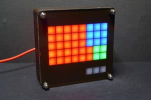
Last December Itead Studio updated their Home Automation product line with a new and different product. The main difference is that it doesn’t have a relay and it’s mainly sensors and no actuator (if we don’t define a notifying LED as an actuator). The Sonoff SC is a sensor station that packs a DHT11 temperature and humidity sensor, a GM55 LDR, an electret microphone with an amplifier circuit and a Sharp GP2Y1010AU0F dust sensor in a fancy case that looks like it was originally meant for a speaker.

The device is packs an ESP8266 as expected and is compatible with the eWeLink app. But, such a collection of sensors, with 3 of them having analog interfaces, cannot be run from the single-ADC ESP8266 so Itead has thrown in a good old ATMega328P to drive the sensors and report the Espressif with the data.

The outside

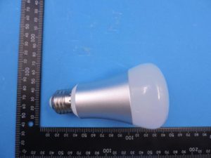
The first thing that draw your attention about the Sonoff SC is it’s casing. It’s kind of a truncated hexagonal-ish pyramid with a round grid on top and a rounded bottom. Seriously, somebody had a good time designing this. It looks a lot like a intricate speaker and actually that’s what it is. The reset/flash button sticks out shamelessly from a hole labelled “Audio” on one side of the enclosure.

20170105_125958s

Side by side with the fake audio hole there is an microUSB connector that’s only for powering the device (no data lines connected) and a microSD slot. The microSD reader is connected to the ATMega328P and I’m not sure what original purpose it has but I can think on a couple of good things to do with it.

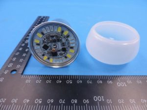
On the bottom you have 4 black screws. Remove them to gain access to the insides of the device.

20170105_125942sThe insides

20170105_131332s

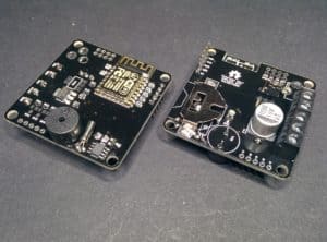
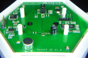
Once the 4 screws are removed it can still be a little tricky to take the PCB out from the enclosure since the button shaft leaves little room to lift the PCB from the plastic holders. Meanwhile you try to remove it, take a look at the components on that bottom side of the PCB. There you can find the controllers and programming headers.

20170105_130308s

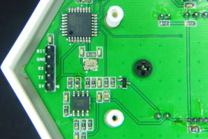
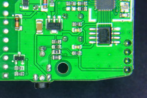
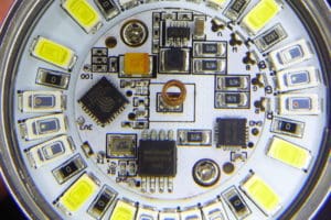
The ATMega328P microcontroller with a 16MHz crystal. The SO-8 IC is a SGM358 dual op-amp used to amplify the electret signal. You can also see a header with 5V, TX, RX, GND and RST.

20170105_130321s

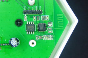
On the opposite site you have the ESP8266 IC with a Winbond 1Mbyte flash memory. You can see the PCB WiFi antena and the programming header with all the needed pins plus the SDA pin. The button is attached to GPIO0 so press it while powering the board to get into flash mode.

20170105_130416s

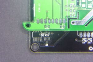
A perspective view fo the bottom side of the PCB. Three more things to note: the jumpers in the center-top of the image connect the RX and TX lines of the ESP8266 and the ATMega328P. Left of that, by the ATMega IC you have an unpopulated ISP header. You will have to solder a 2×3 header here to program the Atmel IC. Also, you have the Electret Mic in the forefront.

20170105_131503s

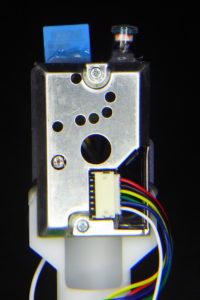
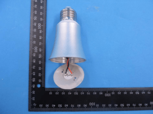
The other three sensors are pleaced on a plastic holder and fit inside the cone of the device. They are hot-glued between them and using standard JST connectors, so replacing them should be no problem…

Upgrading the Sonoff SC

There are a couple of simple, almost out-of-the-box, upgrades you can do to your Sonoff SC. First you can easily replace the DHT11 termperature and humidity sensor with a more precise DHT22 (AM2302) [Aliexpress]. Both sensors are pin compatible. You can read great full comparison of them plus the Sensirion SHT71. The DHT22 is better in accuracy and range to it’s cheaper sibling, but it also has a short life expectancy, so after all it’s a good idea to be able to replace it easily.

20170109_235753s

DHT11 and DHT22 (AM2302) side by side. They are pin compatible.

Off course replacing the sensor is not the full story, you will need to add support for the DHT22 to the firmware. More on this later on.

20170109_235853s

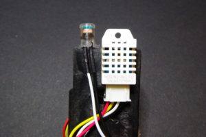
The DHT22 is also bigger than the DHT11. Make sure you place it so it does not protude further than the LDR capsule, otherwise you will have problems fitting everything inside the enclosure back again.

There is also an unused connector in the PCB meant for an LED. It’s driven by GPIO D7 in the ATMega328P through a 2N7002 mosfet in reverse logic (set to LOW to turn on). Remember you have an LED on the PCB as well driven by GPIO13 of the ESP8266 also in reverse logic. The 5V pin is connected directly to the USB supply, so if you have a good power supply you may as well connect here an WS2812 LED strip or ring for some colourful notifications. You will need a GND connection too but there are quite a few available (and properly labelled) on the board already.

20170105_131628s

The LED connector side by side to the dust sensor one.

New firmware for the Sonoff SC

This custom Sonoff SC firmware is released as free open software and can be checked out at my SonoffSC repository on Github.

So after making myself comfortable with the hardware of the device I started putting together some pieces grabbing code from other projects like the ESPurna firmware. The goal was to replace the code in the ATMega328 and the ESP8266 microcontrollers to be able to integrate the Sonoff SC into my home network. That means no cloud, that means MQTT.

While doing that I have added some features that came almost for free since I had already worked on them in other projects: Domoticz support for those that use that home automation platform and a “clap monitor“. Yes. Clap your hands to switch on/off the lights.

Just like the original firmware, this custom firmware monitors temperature, humidity, noise level (in %), dust (in mg/m3) and light (in %).

Communication

First thing was to be able to send messages between the ATMega328P and the ESP8266. Itead Studio provides a simple firmware for the ATMega328P in the Sonoff SC wifi page. The firmware is a good starting point but I don’t like it’s architectured. Everything is too coupled.

So first thing was to create a communications library between both microcontrollers. I started looking for similar solutions and found out the SerialComm library by fjctp. It was almost what I was looking for but I liked the AT commands approach, one char keys are too minimal and naming is important. So I wrote the SerialLink library that allows me to:

  • Compatible with AVR and ESP8266 ICs
  • Define custom commands (the library is agnostic) like AT+TEMP
  • Query command management (AT+TEMP=?)
  • Optional automatic ACK responses
  • Tolerant to noise in the line (debug output from the other controller)
  • Callbacks for get and set values from the application
  • Custom separator (=), terminator (\n) and query (?) chars
  • Currently, it only accepts integer payloads

In the picture below you have a sample of the communication between both microcontrollers. The ESP8266 debug messages are quite verbose but only those starting with AT+… are answered by the ATMegae328P. These are configuration messages “AT+EVERY=60” (set update interval to 60 seconds), “AT+CLAP=1” (enable clapping monitor) and “AT+PUSH=1” (enable message push from the ATMega328P to the ESP8266). Further down the log you start seeing MQTT messages due to push messages from the AVR about a clap code or sensor data.

comms

The SerialLink library is currently bundled into my SonoffSC repository. I will create it’s own repo soon.

MQTT and Domoticz

MQTT and Domoticz integration was easy since most of the code was already there in the ESPurna firmware. I configured the communication link for push messages so in the ESP8266 side I have a callback function that gets all the messages from the ATMega328P and dispatches them to the different outputs.

In this code fragment you can see how message keys are matched and messages are forwarded to three different clients: MQTT, Domoticz and broadcasted to websocket clients like the web interface.

bool commsSet(char * key, int value) {

    char buffer[50];

    if (strcmp_P(key, at_code) == 0) {
        mqttSend(getSetting("mqttTopicClap", MQTT_CLAP_TOPIC).c_str(), value);
        return true;
    }

    if (strcmp_P(key, at_temp) == 0) {
        temperature = (float) value / 10;
        mqttSend(getSetting("mqttTopicTemp", MQTT_TEMPERATURE_TOPIC).c_str(), temperature);
        domoticzSend("dczIdxTemp", temperature);
        sprintf(buffer, "{\"sensorTemp\": %s}", String(temperature).c_str());
        wsSend(buffer);
        return true;
    }

    ...

}

Clap monitor

Now, this is more like a game feature. Don’t know if it’s really useful but it’s certainly fun to play with. Have you ever wanted to move someone by clapping your room lights into romantic mode? Well, this feature is about that.

The algorithm for clapping recognition is somewhat hard if you want to make it reliable, remove false positives and avoid “losing” messages. It’s not certainly suited for a noisy environments (I have kids at home…). My current approach is:
  • The ATMega samples the mic analog output (amplified) in 20ms windows and calculates peak-to-peak values
  • If peak-to-peak value is higher than a certain threshold during N consecutive time windows it flags it as a clap as remembers the current time in milliseconds
  • From the second clap on it stores the time between claps (there is also some debouncing code here)
  • After the last clap times out it checks if it has recorded any intervals (so that it has sensed a minimum of two claps in a row).
  • Clap intervals are coded into binary values. The value always starts with a 1 and each interval pushes a new bit from the right ad shifts everything up. The first interval length is considered a “short” or a 0. If an interval is at least 1.5 times bigger than the first one it is read as a “long” or a 1.
  • Finally the intervals array is reset and everything starts over again

This way I can encode clapping patterns as one byte codes. Two claps are always a “short” so it will be coded as b00000010 or 2. Three claps evenly spaced in time will be a b00000100 or 4. But if you leave a longer time (less than a second) between the second and third claps you get a b00000101 or 5.

I admit it’s somewhat weird but you easily get used to it. “Clap, clap,… clap, clap” (that’s a 10) and switch on the mirror light. “Clap, clap, clap, …. clap” (that’s an 9) and there goes the living room one.

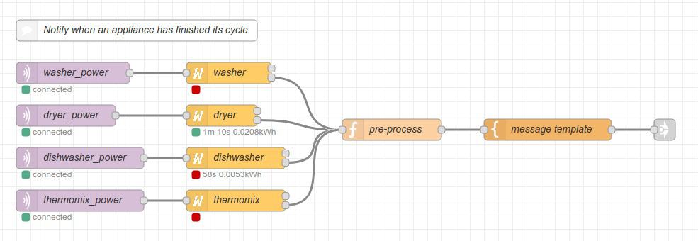
Right now clapping codes are sent by MQTT to a user defined topic. So it’s a matter of having a service somewhere in you local network translating them to MQTT topics to perform different actions. This is a my test flow in Node-RED at home:

nodered-clap

And the code of the “matching” function node is below. Those are ESPurna devices, payload 2 means toggle relay.

if (msg.payload == 9) {
    msg.topic = '/home/living/lamp/relay/0';
    msg.payload = 2;
} else if (msg.payload == 10) {
    msg.topic = '/home/mirror/light/relay/0';
    msg.payload = 2;
} else {
    msg = null;
}
return msg;

And in the future…

There are some features I’d like to add in the future. One thing is that the device has a microSD slot connected to the SPI lines of the ATMega328P. Log sensor data to an SD card could be an option here for non-connected mode.

20170105_131406s

Also I’d like to be able to map clap codes to MQTT topics, hence not needing an external service like NodeRED to do that.

A neat feature would be to be able to OTA flashing the ATMega328P form the ESP8266. It should be possible with a minimum hardware hack: wiring the RST pin in the ATMega328P header to the SDA (GPIO2) pin in the ESP8266 header to reset the AVR programatically.

Also, there are some spare GPIOs available in the board that could be used to add more sensors (the SPI header exposes 3 digital pins, but shared with the SD). Ideas?

Flashing the ESP8266

Flashing the ESP8266 is very easy since the header close to it has all the required connections (3V3, TX, RX, GND) and the button is connected to GPIO0. Press and hold the button while powering the board to set the ESP8266 into flashing mode. You will have to remove the TX jumper in the board to avoid the ATMega328P to interfere in the upload process.

My recommendation is to flash an OTA enabled firmware as soon as possible as use OTA from then on to update the ESP8266 firmware. This way you can keep the jumpers in place and debug the communications to the AVR IC.

Flashing the ATMega328P

The ATMega328P comes flashed with the Arduino bootloader so all you have to do is connect a USB to UART programmer [Aliexpress] to it and flash it from the Arduino IDE or PlatformIO. Notice that labels in the header are from the programmer point of view (weird). So wire RX to your programmer RX, TX to your programmer TX and RST to DTR. Use 5V logic. Also, you don’t want the ESP8266 interfere with the upload so remove the RX jumper that connects both microcontrollers. Actually remove both of them or the ESP8266 might complain with so much noise.

sonoff-sc-pcba

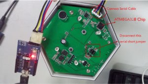
The ATMega328P comes with the Arduino bootloader so you can flash it using a USB to UART programmer (and FTDI-like). You will have to unbridge the connections to the ESP8266 to do it to avoid the ESP8266 interfere in the upload process. Photo by Itead Studio.

But, if you have an AVR programmer like the USBASP v2 [Aliexpress] below, it might be a better option to program the ATMega328P using the unpopulated ISP header in the board. This way you won’t have to disconnect the jumpers between both controllers and have a stable test bed

20170110_005549s

The USBASP programmer I use to flash the firmware in the ATMega328P

Debugging

I’m using the ISP header to flash the ATMega328P and OTA to update the firmware in the ESP8266. This way I have everything connected and I can debug both microcontrollers using two USB to UART boards.

I use only RX lines connecting the RX of programmers to the RX pins in both headers (remember: RX to RX). Grounds are shared through my computer, but you might have to connect those too for better reliability.

20170110_005853s

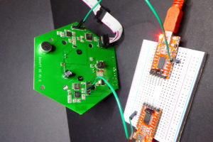
Test and debug. ISP for uploading ATMega328P firmware, OTA for the ESP8266 and two RX llines to get debug messages from both microcontrollers.
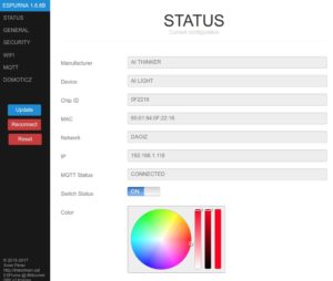
Interface

The application web interface is stored in the ESP8266 using the same compression techniques I use for the ESPurna firmware. Right now you can:

  • Check the current values from the sensors
  • Configure up to 5 different WiFi networks (including the option for static IP)
  • Configure the MQTT connection and topics for the different sensor data
  • Configure the integration with Domoticz
  • Change the hostname (used for the DNS discovery feature: http://myhostname.local)
  • Change the sensor update interval
  • Enable/disable the clap monitor feature

The interface is based on jQuery and PureCSS. Here you have screenshots from the pages in the interface so you can get a better idea of what it can do at this moment.

sonoffsc-0-1-0-status

sonoffsc-0-1-0-general

sonoffsc-0-1-0-wifi

sonoffsc-0-1-0-mqtt

sonoffsc-0-1-0-domoticz

Right now it’s a fully working firmware replacement for the Sonoff SC. You will maybe miss some features from the original firmware. Let me know which ones. Use Github (link below) to report issues or feature requests.

This custom Sonoff SC firmware is released as free open software and can be checked out at my SonoffSC repository on Github.

Any comments are more than welcome.

The post Sonoff SC with MQTT and Domoticz support appeared first on Tinkerman.


Power monitoring with Sonoff TH and ADC121

$
0
0

Lately I’ve been quite busy with the ESPurna firmware. It’s growing bigger and gaining some momentum. It’s really fulfilling to see other people using it and reporting back. But at the same time it’s very time consuming. Last Saturday I released version 1.5.0 with some new functionalities and bug fixes and I decided to use some of my free time over the weekend to work on a project that’s been waiting for a month in the shelf.

A few weeks ago I was playing with the Sonoff TH and I wrote a post about its sensor interface and the possibility of using lots of different digital sensors, including I2C sensors since the board can be easily hacked to export 2 digital pins over that interface.

And having I2C not only increases the number of potentially usable sensors but also opens the possibility of using I2C Analog to Digital converters to overpass the lack of analog inputs in the device. Here it comes the Texas Instruments ADC121 (datasheet), an 12-bit precision ADC with I2C support priced 2.74€ in quantities of 1.

Hacking the Sonoff TH

In my previous post about the Sonoff TH I already mentioned what to do to export a second GPIO in the 2.5mm jack output. It’s really simple, a 0Ohm resistor to bridge a pad (or a blob of solder) and a pull-up resistor if you plan to use it as I2C.

Hardware modifications to a Sonoff TH16

Two 0805 resistors (the noticeably bigger ones). A 0Ohm one to bridge the pad and connect the first ring to GPIO4 and the second one is a 5k1Ohm pull-up.

The think that puzzles me is that the pads for those 2 resistors are already there, but unpopulated. Obviously the engineers at Itead Studio designed a connector with 2 digital GPIOs but during the manufacturing it was decided to leave only one accessible. After all Itead is selling 2 sensors for the TH that both use just one digital pin, so I guess it was a money-driven decision, but still… it’s only two more resistors!

ADC121 board with connector for a 3.5mm CT jack

The idea was to have a small breakout board with an ADC and a more standard 3.5mm jack, the same size most of the non-invasive current clamps out there use. I decided to do a board with a single channel ADC121C027 by Texas Instruments.

Sonoff ADC121 board

The two sides of the Sonoff ADC121 board. It has pads for optional I2C pull-ups and a burden resistor in case your CT doesn’t have one already built-in. Also there is a pad to select the I2C address of the device.

The decision on what ADC to use was between the ADS1115 I already had experience with and the ADC121 family, specifically the ADC121C021 in VSSOP package and the ADC121C027 in SOT package. The ADS1115 has 4 16-bit ADC channels (or 2 differential) and 4 hardware selectable possible addresses. The ADC121 on the other side is a single channel 12-bit ADC with 3 possible I2C addresses. But they are half the price…

Since the goal was to create a current sensor compatible with the Sonoff TH and most of the times you would like to measure the current flowing through the same Sonoff, one channel is enough. Besides the I2C protocol allows to add multiple slaves to the same bus so there is always the possibility to stack different boards to connect different current clamps to the same Sonoff TH. Actually, modern houses here use to have 3 different power phases, so that seems a good number for the maximum number of addresses I could use in a single device.

So I decided to go for the cheaper ADC121 since it has 3 possible addresses and 12-bit ADC is enough for the measurements I want to do. I have a 30A/1V YHDC clamp and 12bit resolution over a 3.3V reference voltage means around 5-6W per unit (230V * 30A/V * 3.3V / 2^12 ~ 5.56W). Granted I will have some noise so it won’t be able to detect LED lamps or small home electronics like mobile charges and such, but it will be OK for traditional bulbs (yes, we still have them), heaters, washing/drying machines, fridges, microwaves,…

20170123_011637s

The board populated. The holes serve as strain relievers and they do their job very well. Also note there are no pull-ups in the board since the Sonoff TH already have them (in both lines now that I have added them)

Sonoff ADC121 board bottom

On the bottom side there is the ADC121, some decoupling capacitors and the voltage bias (R5 and R6). Also the burden resistor is unpopulated since my current clamp has one built-in.

To solder the ADC121 I used solder paste and a hot gun. I’m still newbie using it but I’m improving. Actually, the hardest part was to know the right orientation for the IC. The footprint I had has a dot mark by pin #1, but the SOT6 I received has no dots anywhere, just an X31C label over a line running along the long side.

After investigating a bit I learnt that, usually, if you place the part so you can read the label the pin #1 is in the bottom-left of the IC. Good to know!

Sonoff ADC121 OSHPark render

In the render OSHPark generates you can clearly see the dot mark in pin #1

20170123_011915s

See the label? If you can read it (so it’s not upside down) the bottom-left pin is pin #1

EmonLiteESP with ADC121 support

The EmonLiteESP library is released as free open software and can be checked out at my EmonLiteESP repository on Bitbucket.

Once I had the board I wanted to write some code to test it. There are no ADC121 libraries out there, at least none the I have found. But the functionality I needed was so simple I decided to go straight to the code.

You might know that some time ago a wrote a simple power monitor library for the ESP8266 platform inspired in the EmonLib library for Arduino. The EmonLiteESP library does not implement all the functionality of the original library for Arduino and it’s not API compatible. It only monitors current, no voltage, so you can not get active power, only apparent power. But on the other side the reading is not tied to a specific analog GPIO. Instead you have to define a function callback that will return the analog reading using whatever sources you want, in particular using an I2C ADC.

It might sound complicated, but it’s not. The simplest function would be that returning the value from an analog pin:

unsigned int currentCallback() {
    return analogRead(CURRENT_PIN);
}

You will then pass this function to the library constructor so it knows how to get the reading. Much more flexible. Because now I want to get the value from an ADC121:

unsigned int currentCallback() {

    unsigned int value;

    // Ask for a reading
    Wire.beginTransmission(ADC121_ADDRESS);
    Wire.write(ADC121_REG_RESULT);
    Wire.endTransmission();

    // Get value (12 bits in 2 bytes)
    Wire.requestFrom(ADC121_ADDRESS, 2);
    if (Wire.available() <= 2) {
        value = (Wire.read() & 0x0F) << 8;
        value |= Wire.read();
    }

    return value;
}

You see, the rest of the code does not change. This pattern is called the strategy pattern in books because it lets you define what strategy the library should use to execute a certain action, like getting an analog value.

Using the Brzo I2C library

The Wire library is part of the Arduino Core for ESP8266 and is API compatible with the Arduino library with the same name. But recently I knew about an implementation of the I2C protocol written in assembly (!!!) specifically for the ESP8266 platform by Pascal Kurtansky. The Brzo I2C library is open source and it’s available in the PlatformIO library manager.

What does it mean it’s written in assembly? Well, basically it means that it’s fast. How fast? A lot faster than the Wire library. In the EmonLiteESP repo you can find two examples for the ADC121, one using the Wire library and a second (adc121_fast) using Pascal’s implementation. Running the example using the Wire library with 1000 samples takes 544ms for each reading. The same with the Brzo I2C library takes only 85ms!! That’s 6.4 times faster!! Amazing. Actually you have to be sure you get at least one full period of the current wave. For a 50Hz system that’s 20ms. So 1000 samples are still 4 full periods.

The problem with the 544ms, aside from the obvious fact that it takes more time, is that 1) you get less samples per period, so your wave representation is very pixelated, so to say, and 2) you can get into problems with your wifi connection or other services that might need more attention.

Let me copy here the full example of the ADC121 using the Brzo I2C library. Some things to notice:

  • Same as with the Wire library for ESP8266 you can choose which two GPIOs to use as SDA and SCL. In the Arduino boards (in ATMega328 controllers) these are fixed in hardware.
  • The Brzo I2C library always uses buffers to send and receive data.
  • You have more fine grain control over the protocol, like SCL frequency and clock stretch time.
  • The current callback I talked about before is implemented here as a lambda function, that’s the “[]() -> unsigned int { …” stuff. There is no need to do it this way.
/*

EmonLiteESP ADC121 Example using Brzo I2C library

Energy Monitor Library for ESP8266 based on EmonLib
Currently only support current sensing

Copyright (C) 2017 by Xose Pérez <xose dot perez at gmail dot com>

This program is free software: you can redistribute it and/or modify
it under the terms of the GNU General Public License as published by
the Free Software Foundation, either version 3 of the License, or
(at your option) any later version.

This program is distributed in the hope that it will be useful,
but WITHOUT ANY WARRANTY; without even the implied warranty of
MERCHANTABILITY or FITNESS FOR A PARTICULAR PURPOSE.  See the
GNU General Public License for more details.

You should have received a copy of the GNU General Public License
along with this program.  If not, see <http://www.gnu.org/licenses/>.

*/

#include <Arduino.h>
#include "EmonLiteESP.h"
#include "brzo_i2c.h"

// -----------------------------------------------------------------------------
// Configuration
// -----------------------------------------------------------------------------

// I2C CONFIGURATION
#define I2C_SDA_PIN             4
#define I2C_SCL_PIN             14
#define I2C_CLOCK_STRETCH_TIME  200
#define I2C_SCL_FREQUENCY       1000

// ADC121 Address
#define ADC121_ADDRESS          0x50

// ADC121 Registers
#define ADC121_REG_RESULT       0x00
#define ADC121_REG_ALERT        0x01
#define ADC121_REG_CONFIG       0x02
#define ADC121_REG_LIMITL       0x03
#define ADC121_REG_LIMITH       0x04
#define ADC121_REG_HYST         0x05
#define ADC121_REG_CONVL        0x06
#define ADC121_REG_CONVH        0x07

// If you are using a nude ESP8266 board it will be 1.0V
// If using a NodeMCU there is a voltage divider in place, so use 3.3V instead.
#define REFERENCE_VOLTAGE       3.3

// Precision of the ADC measure in bits. Arduinos and ESP8266 use 10bits ADCs.
// The ADC121 is a 12bits ADC
#define ADC_BITS                12

// Number of decimal positions for the current output
#define CURRENT_PRECISION       2

// This is basically the volts per amper ratio of your current measurement sensor.
// If your sensor has a voltage output it will be written in the sensor enclosure,
// something like "30V 1A", otherwise it will depend on the burden resistor you are
// using.
#define CURRENT_RATIO           30

// This version of the library only calculate aparent power, so it asumes a fixes
// mains voltage
#define MAINS_VOLTAGE           230

// Number of samples each time you measure
#define SAMPLES_X_MEASUREMENT   1000

// Time between readings, this is not specific of the library but on this sketch
#define MEASUREMENT_INTERVAL    10000

// -----------------------------------------------------------------------------
// Globals
// -----------------------------------------------------------------------------

EmonLiteESP monitor;

// -----------------------------------------------------------------------------
// Energy Monitor
// -----------------------------------------------------------------------------

void powerMonitorSetup() {

    // Init I2C protocol
    brzo_i2c_setup(I2C_SDA_PIN, I2C_SCL_PIN, I2C_CLOCK_STRETCH_TIME);

    // Set the ADC121 fo manual readings (no automatic sampling)
    uint8_t buffer[2];
    buffer[0] = ADC121_REG_CONFIG;
    buffer[1] = 0x00;
    brzo_i2c_start_transaction(ADC121_ADDRESS, I2C_SCL_FREQUENCY);
    brzo_i2c_write(buffer, 2, false);
    brzo_i2c_end_transaction();

    // Setup power monitor
    monitor.initCurrent([]() -> unsigned int {

        unsigned int value;
        uint8_t buffer[2];

        // Ask for a reading
        brzo_i2c_start_transaction(ADC121_ADDRESS, I2C_SCL_FREQUENCY);
        buffer[0] = ADC121_REG_RESULT;
        brzo_i2c_write(buffer, 1, false);

        // Read the value
        brzo_i2c_read(buffer, 2, false);
        brzo_i2c_end_transaction();
        value = (buffer[0] & 0x0F) << 8; value |= buffer[1]; return value; }, ADC_BITS, REFERENCE_VOLTAGE, CURRENT_RATIO); monitor.setPrecision(CURRENT_PRECISION); } void powerMonitorLoop() { static unsigned long last_check = 0; if ((millis() - last_check) > MEASUREMENT_INTERVAL) {

        unsigned long start = millis();
        double current = monitor.getCurrent(SAMPLES_X_MEASUREMENT);
        Serial.printf("[ENERGY] Sampling time: %ldms\n", millis() - start);
        Serial.printf("[ENERGY] Power now: %dW\n", int(current * MAINS_VOLTAGE));

        last_check = millis();

    }
}

// -----------------------------------------------------------------------------
// Main methods
// -----------------------------------------------------------------------------

void setup() {
    Serial.begin(115200);
    powerMonitorSetup();

}

void loop() {
    powerMonitorLoop();
    delay(1);
}

The post Power monitoring with Sonoff TH and ADC121 appeared first on Tinkerman.

AiLight – A hackable RGBW light bulb

$
0
0

Some weeks ago a tweet by Manolis Nikiforakis (@niki511) with the #ESP8266 hashtag drew my attention. Manolis had just received a “smart lamp” branded by Ai-Thinker, the AiLight. Yes, the same Ai-Thinker that has sold millions of ESP8266 based modules. Chances were it had an ESP8266 microcontroller inside. Too good not to buy one and take a look at the inside.

Manolis shared the link where he bought his at Ebay for a bit more than USD 10 plus shipping. Unfortunately it’s out of stock there and there are amazingly few other places where you can buy it. I only found the same product with prices from 12 to 18€ at Ebay as DIY Smart Wifi Light Bulb [Ebay] or at Aliexpress sold as “DIY Wifi LED Bulb E27 5W AC110-240V lampada LED Dimmable Bulb Lamp Remote Control Led Spot Light for iPhone Android Phones” or “1Pcs E27 Dimmable LED Light Bulb Smart Wireless Wifi AC 110V 220V LED Corn Lamp Cold White Warm White Dimming LED Spotlight” [Aliexpress]. Don’t you love those seo-ugly names?

I actually bought two because you never know. And they arrived last Thursday. It took me less that 1 minute to open one of the boxes, pop out the cap and take a look at the inside just to see what I already knew. Time to play 🙂

Some pics to start

I’m not good or fond of “unboxings” but since it’s a hard to find product I might add here some pics of the boxing and the light bulb.

Each light bulb comes in a light brown box (149x105x67mm if you ask) labelled “WiFi Light” on both faces and with a light bulb pic and a mysterious empty square (?). Looks like a place to mark the variation (they sell them in silver and gold finish), but the sticker with the color is actually on the other side of the box…

20170226_222418x
There is a label on the bottom of the box with the legend “M1636_SVWIFI” and the usual “Made in China”. I guess SV means “silver” so the model would be “M1636” (I actually found some of the references above looking for this model number).

20170224_210311x

Inside the box there is a simple two fold paper with Chinese instructions to download the app to control the device on your cellphone. Two things to note: first the funny guy pictured in the paper. I’m not much into Chinese culture but he looks like a 60yo nerd. And then the baseline “If you are not an engineer”. What does it mean? Maybe they meant it’s a product for everybody, you don’t need to be an engineer. Or maybe it’s a “use the provided app unless you plan to hack it”?

20170226_222514x

20170226_222501x

And finally the light bulb it’s a copy of the Philips Hue [Amazon] without the logo, with WiFi instead of Zigbee and at a fraction of the price.

20170224_210255x

20170224_210336x

Taking a closer look

The bulb cap is not glued, it just fits in. Just pull with a bit of strength and it will pop out. After removing it you have full access to the PCB.

20170224_210402x

The PCB it’s actually 2 PCBs. The outer one has 8 high power white LEDs, 6 red LEDs, and 4 blue and 4 green LEDs. The inner PCB holds the logic circuit with an ESP8266EX microcontroller and a Winbond 25Q80BVSIG 1MByte flash memory chip. These are the usuals suspects.  There is also a SOT23-6 package labelled ADJG and a 20 pin IC labelled MY9291QD.

20170224_210528x

There are also 5 pads labelled 3V3, GND, RX, TX and IO0. Too good to be true. They were probably used at the factory to flash the stock firmware on the controller using a gig with pogo pins. Anyway it looks easy to solder some thin wires and upload a custom firmware.

The only doubt left is how to control the LEDs. Googling the MY9291 chip throws one perfect match: the My-Semi MY9291 LED driver. Bingo. But the datasheet lacks any information about how to use it…

Digging on the Internet

Aside from the product in Ebay or Aliexpress there is little information about these light bulbs in the Internet. But with the information I already had I dug a little bit on the Internet and found two interesting pages.

FCC aplication

On one hand I there is the FCC application by Ai-Thinker dated November 9th, 2016. In the application, aside from some interesting documentation like the cellphone app “Tuya Smart” user manual, there are plenty of images from the inside of the product.

external-photos-339edde5x

Picture from the FCC application

As you can see in the pictures below the PCB is glued and behind it there is a small AC/DC transformer. The bulb itself is 116mm long and 62mm diameter.

internal-photos-687cf489x

Picture from the FCC application

2x

Picture from the FCC application

mosaic3x

Picture from the FCC application

Noduino OpenLight

On the other hand, going down the path of the MY9291 reference you quickly found the Noduino OpenLight wiki page at JacksLab, by Jack Tan, alias comcat, the guy behind the Noduino project. In that page you have lots of information about the light bulb including sample code and the schematics of (part of) the circuitry by Jack.

1024px-noduino-open-light-v2-4-sch

Apparently Jack Tan or the Noduino team is behind this product somehow. Anyone knows what relation is there between Noduino and Ai-Thinker? In the Noduino OpenLight page there are pictures of a virtually identical light bulb in the shape but also with the same PCB. But not only that.

You have an precise description of the LED PCB and reference to the MY9291 LED driver by Taiwan Mingyang (hence MY-Semi). It also confirms that the AC/DC transformer outputs 12V at 1A max. And describes two different step-down ICs. The MP1470 and the MP2359, both by MPS. The MP1470 has the ADJ mark.

But most interesting, the page includes a section on how to compile your own firmware for the OpenLight based on the Noduino SDK.

A library and a little bit of code

I checked out the Noduino SDK and there it was: a C driver for the MY9291. That’s everything I needed. By the way, I noticed the Noduino SDK includes my HLW8012 library (but not the most up-to-date version).

The driver is licensed GPLv3 and copyrighted to Maike Labs, Maike Labs is icamgo and icamgo is Noduino. You can use the driver as is but I took some time to encapsulate it in a library with some helper methods to manage the color and state of the LEDs. I have tested it with the ESP8285 in the AiLight but should work on ATmega328 or other AVR chips.

The MY9291 library for Arduino ESP8266 is released as free open software and can be checked out at my my9291 repository on Github.

Let me show you a simple example on how to set red LED on at 100% duty cycle (MY9291_COMMAND_DEFAULT defines 8-bit color depth so 255 means 100%):

#include <my9291.h>

#define MY9291_DI_PIN   13
#define MY9291_DCKI_PIN 15

my9291 _my9291 = my9291(
    MY9291_DI_PIN, 
    MY9291_DCKI_PIN, 
    MY9291_COMMAND_DEFAULT
);

void setup() {
    _my9291.setColor((my9291_color_t) { 255, 0, 0, 0 });
    _my9291.setState(true);
}

void loop() {}

Flashing it

It might look hard to solder those small pads in the beginning but it’s actually really simple. Get a 5 wire cable and remove 1-2mm of insulation from the wires, tin them a bit. Apply a hot wire on the pads and leave a small drop of tin on them too. Then just touch each wire with a pad and heat them together for a fraction of a second.

20170224_105810x

Connect the wires to you FTDI (or alike) board. TX to RX and RX to TX. Connect GND and IO0 to ground and finally 3V3. Once you plug your programmer to the computer the board will boot into flash mode. While you are flashing it you can remove the IO0 connection. Upon reboot it will enter normal mode and you should see the debug messages in the screen.

ESPurn’d

And of course it has been ESPurn’d. Version 1.6.7 of the ESPurna firmware supports the Ai-Thinker AiLight / Noduino OpenLight. You can turn on/off the light bulb and select the color from the web interface or you can do both things via MQTT from Node-RED for instance.

ailight_espurna

The post AiLight – A hackable RGBW light bulb appeared first on Tinkerman.

Fenderino, the coolest guitar

$
0
0

Last February 7 I attended a workshop at a the SokoTech in Barcelona to assemble my own Fenderino, the coolest guitar ever (my knowledge about guitars is very limited, so take this sentence with a grain of salt).

The guitar is actually a shield for the Arduino UNO and has been designed by the people at abierto.cc, an initiative aimed to provide open(-sourced) tools for educators, created amongst others, by David Cuartielles, co-founder of Arduino. The shield is inspired by the works of two very good friends of mine: Marc Sibila (@marcsibila) and Jordi Divins (@jdivins). You really should be following these guys, they are doing very special things as Instròniks.

The Fenderino

The shield itself is a beauty.

The shape resembles a Fender Stratocaster and the purple colors would appeal Prince himself. But that’s not everything. A few details make it really shine. The 4 LED brick for the visual notifications is one of those components you invent a project just to be able to use them. The item is a KINGBRIGHT L-875/4IDT and Cuartielles pointed me to the only source I have found for it: farnell.com. It sells for 1.34€ a piece.

The other detail that really stands out is the common cathode 4x 200ohm resistor array. Not as uncommon as the LED array, it limits the current to the LEDs on the array but it doubles as the bridge of the guitar. Nice detail.
20170210_145715s20170210_145529s

The 9 buttons cover a complete octave plus one note (from C to C) and the two potentiometers are used in the sample sketches to change the octave (actually the pitch of the first button) and the volume. There is also a handy 3 positions switch to use different configurations.

20170210_145301s

Finally the output can be the builtin high quality buzzer or your headphones (or you HiFi system) connected to the 3.5mm jack out.

20170210_145511s20170210_145517s

Open Source Software & Hardware

On the workshop we had the opportunity to test different sample sketches, from very simple ones to test the welding connections to scales, polyphonic sounds and a simple but amazing voice synthesizer using the Talkie library by Peter Knight.

Hardware files (KiCAD) and sketches for the Fenderino will be open source. They are not yet available but Cuartielles confirmed me this point just yesterday. As you can see the hardware is licensed CC-SA-BY-NC so basically you can copy and modify it as long as you do proper attribution and you use the same license and don’t make profit out of it.20170423_004500s

Talking MIDI

Playing the guitar was so fun from the very first moment! I was eager to contribute somehow to the project.

At home, we got a new keyboard piano for Christmas and we had it connected to a tablet with the Synthesia app to learn to play some songs. It had been my first contact with the MIDI interface and I had that feeling I could do some fun projects with it. So I started looking at how to turn the Arduino into a MIDI device.

As it turns out, adding MIDI to a USB-capable microcontroller with Arduino is very easy. There are several libraries available. Mainly the MIDIUSB by Gary Grewal & Arduino. But you have to have an USB capable Arduino, like the Leonardo. What if you want to use a Uno?

The Arduino UNO has a second microcontroller on board that handles the USB communications. An Atmel ATMega8u2 or ATMega16u2. That controller talks USB to UART only. But the good thing is that it is a programmable microcontroller (at least in the official Unos, counterfeits sometimes use an FTDI chip or alike which is not reprogrammable).

What we need is to flash that helper microcontroller with a firmware that talks MIDI. Well, there is an open source project that does just that: the HIDUINO. The HIDUINO project “(…) provides a true USB-MIDI device for plug-and-play compatibility on Windows, OSX, and Linux – just like a commercial MIDI controller”. Sounds good.

There are two drawbacks. First you will need an AVR programmer to flash the HIDUINO firmware into the ATMega16u2. There is an ISP header just by the microcontroller to do so.

Second you will need a AVR programmer to flash the ATMega328P from then on since the USB handler IC is no longer doing its job as USB to UART bridge. Actually you only need one AVR programmer so it’s not that much hustle and you can always flash the original firmware for the ATMega16u2 and get back your Arduino UNO.

To flash the ATMega16u2, first checkout the HIDUINO project and grab the arduino_midi.hex file in the compiled_firmwares folder. Connect your programmer like in the pic below. I’m using an USBASP v2.0 [Aliexpress] here with a 10-pin to 6-pin flat cable, an AVRISPMKII [Aliexpress] will also do. To flash it the fast is to call avrdude from the command line (you might need to specify absolute paths for the avrdude binary or config file):

avrdude -v -p atmega16u2 -C avrdude.conf -c usbasp -Pusb -F -U flash:w:arduino_midi.hex -U lfuse:w:0xFF:m -U hfuse:w:0xD9:m -U efuse:w:0xF4:m -U lock:w:0x0F:m

img_20170422_235850s

Flashing the sketch is very similar, you can do it from the IDE but again it will be faster to do it from the console:

avrdude -v -p atmega328p -C avrdude.conf -c usbasp -Pusb  -U flash:w:firmware.hex:i

Check the image to connect the 6-pin flat cable in the right orientation.

img_20170422_235916s

Firmware

The Fenderino MIDI sketch will probably be available as an example from the abierto.cc repository. But if you are curious you can check my repo with only the MIDI example I had worked on.

The Fenderino MIDI sketch is released under the GPLv3 license and can be checked out at my Fenderino MIDI repository on Github.

And play!

Left to right: David Cuartielles, me and Marc Sibila at SokoTech. Uma is the canine in residence.

Left to right: David Cuartielles, me and Marc Sibila at SokoTech. Uma is the canine in residence.

You can now buy the Fenderino shield from the abierto.cc store.

The post Fenderino, the coolest guitar appeared first on Tinkerman.

Slices of a clock

$
0
0

There are so many ways to tell the time. DIYers have been doing clocks since the Ancient Egypt (obelisks lacked portability, thou). Every modern maker has a clock amongst her first projects. I have done some myself, including a fibonacci clock, a wordclock with a fancy green matrix effect and an unreleased project that hopefully will see the light someday soon.

But recently I came back to the idea behind the wordclock before, to extend it in different ways:

  • Replace the ATMega328P with an ESP8266 (NTP support and user interaction)
  • Smaller sizes (8×8 LED matrices)
  • Smaller PCB, less buttons
  • Add buzzer for alarms
  • Replace the 3D printed part with a wooden grid cut in laser
  • Completely closed enclosure, better presentation
  • Fix some issues with the original board (like the lack of a beefy capacitor across the LED matrix power lines).

20170426_224545s

Shrinking the PCB

One of the goals was to be able to create smaller displays using 8×8 LED matrices instead of the original 16×16. They are much cheaper and almost the same fun. The 16×16 I was using are the flexible type you can find on Ebay or Aliexpress for about 40-50€.

The 8×8 ones are also available for 7-9€ at Ebay and Aliexpress and have a smaller pitch (8mm versus 10mm for the 16×16 RGB LED matrices). This allows for a smaller version so I decided to design a PCB with the same features but a 50x50mm size. The controller board sports an ESP8266 ESP-12E [Aliexpress, also on Ebay] and a DS1337S RTC [Aliexpress and Ebay]. A buzzer for alarms and connectors for a WS2812 matrix with a beefy capacitor across the power lines.

The DaClock board is released under the Creative Commons Attribution-ShareAlike 3.0 Unported License (CC-BY-SA 3.0) and follows the terms of the OSHW (Open-source hardware) Statement of Principles 1.0. It can be checked out at my DaClock board repository on Github.

daclock-3-0-schema

20170426_110903s 20170430_220914s

SeeedStudio Fusion PCB service

You can use the latest gerblers from the repository or open the project using Eagle +8.0. I sent the gerblers to fab using SeeedStudio Fusion PCB service. It is the first time I use their PCB service but I have already sent a couple more projects to them, including a PCBA service and I plan to do a review about it soon.

Quality of the PCB is really good and price/quality ratio is hard to beat. I like the fact that you are not limited to the green color for the cheapest price tag: green, blue, red, yellow, black, white, they all cost the same and for a standard board under 10x10cm and 2 layers the price starts at USD 4.90 (USD 12.90 lead free) for 10 pieces!!

20170426_111523s

The slices PCB in black looks awesome. The only small glitch I noticed is a small (0.3mm) shift on the silkscreen. Not critical by any means.

20170426_111048s

Not the same board but the same Eagle part, the black one from SeeedStudio is slightly shifted towards the top left corner in the picture.

You can check the bill of materials at the README page in the repo for the rest of components.

Slices

Well, here’s where the name comes from.

My wordclock project had some very good reviews. People at the Mini Maker Faire in Barcelona last year loved it for the display effects and the overall built. “You should be selling it” was a common advice. The only issue someone reported was that it has an open enclosure (that sounds like an oxymoron). So I started thinking about a case for the electronics to prevent them from gathering dust.

On the other hand I wanted to get rid of the 3D printed part, the grid that serves as an isolator between LEDs. So I tried to laser cut it on a 5mm MDF board and the result is much better. 5mm thickness are enough to allow the light to cover the entire 9x9mm square and it looks nicer (better finished), easier to build because I’d be already using a laser cut for the rest of the pieces and much cheaper: a few cents versus a few euros for the 3D printed part, only in material.

20170502_080914s

I love the color of MDF after a session of laser cut!

And to close the box I designed simple hollow layers inspired (again) on the Pibow cases by Pimoroni. The only drawback is that you waste a lot of wood but luckily you can fit 4 layers of the smaller version inside the hollow layers of the 16×16 version since they are smaller than half the length/width (half the LEDs in each direction and smaller pitch).

The end result is a layered, “sliced”, box with room for the LED matrix and the electronics. The layers from front to back are:

  • a smoke colored acrylic layer cut with a laser cutter
  • a diffusor, a thin white paper sheet
  • the LED isolator grid, laser cut in MDF
  • the LED matrix
  • LED matrix frame in MDF for the 8×8 version
  • MDF hollow layers to allow room for the electronics
  • the controller
  • MDF again with holes for the power connector and button

20170426_124503s

20170426_140239s 20170426_140246s

20170426_140325s

To cut the layers I have used the Laser Spirit GE 100W at the Ateneu de Fabricació de Les Corts, one of the three public fablabs in Barcelona: Xarxa d’Ateneus de Fabricació de Barcelona.

The Slices case models (in OpenSCAD format) and the code examples below are released as free open source software & hardware under the GPLv3 licence. You can checked them out at my Slices repository on Github.

Coding clocks and more

Time for the code. I’m using the framework of my ESPurna project to add basic functionality (WIFI, WebServer, NTP, MQTT,…). On top of that I’m adding a matrix manager based on Adafruit’s NeoMatrix library and a driver manager. Each “mode” is handled by a “driver”. Drivers have common methods like setup, start, stop and loop that the driver manager is responsible to call when necessary.

NOTE: the code is still a work in progress.

Basic clock

A really basic clock, either static (like in the picture) or scrolling for 8×8 displays. I’m using the built-in font for Adafruit GFX library but I’d really want to use a thicker one (sans bold or similar). So far I have not been able to find or create a font for the GFX library that suits me. I’d like it to be 7 or 8 points height, easy to understand by a kid and with the full character set, including accented characters. If you happen to know of such font for this library, please let me know!

20170501_225614s

Wordclock

Not the same wordclock as in my previous project, this one scrolls the hour in a readable text. Currently only in catalan language but, believe me, english or spanish are waaaay easier.

Fibonacci clock

First thing I thought when I saw this Kickstarter campaign was “I want one!”. Next thing was “F**k! $100”. An still the next one: “I could build it myself”. Actually, Philippe Chrétien released the code and build instructions in Instructables even before the Kickstarter campaign, so anyone can build hers. Even if you are not good at electronics, for instance, you can buy certain parts from Philippe’s.

So I built my own. I have never written about it here but here you have a picture:
20160108_170107s

Instead of CNC’d thick wood I used MDF and a laser cut. The overall finish is good but improvable. Anyway I thought it could be easier to do with the “Slices”.

20170426_224545s

10:28, obviously

Since the fibonacci clock has a resolution of 5 minutes (you cannot read 19:33, but 19:30 or 19:35) I added the small “dots” at the bottom to account for minutes to add to every 5-minutes block.

Problem here is that you have to know the sizes and positions of each block to read it since they are built from several pixels each. So I cut off several separators from the MDF grid with an exacto knife [Ebay] to draw the different squares of side 1, 1, 2, 3 and 5 respectively and make it clearer:

20170428_031306s

2:55, who would have tell?

Binary clock

The classical geek clock. Hours, minutes and seconds in a BCD format, each column represents a digit of the HH:MM:SS string in binary.

20170426_224506s

22:27:48, easier then the fibonacci clock, rigth?

Game of life

Because why not? New cells are painted green and old ones blue. The game and its inhabitants are mesmerising.

20170502_082956s

Drawing canvas

And finally a little game for my daughters, draw something on the computer and see it in the LED matrix. Currently you can only choose the color and paint the pixels one by one. There is no eraser (you can erase the whole matrix instead). After a couple of drawings my eldest daughter wrote a TODO list for me: allow erasing pixels individually, add a color picker and save images so it can show a slideshow of them.

20170501_225529s


Any other clocks you can think of that could be represented in a LED matrix? A good thing about the ESP8266 is that I still have plenty of room to add more drivers…

The post Slices of a clock appeared first on Tinkerman.

Grid-eye camera (sliced, of course)

$
0
0

Tindie is a great place to find uncommon electronic components or weird/interesting boards. I use to stroll around it’s products to basically see what’s new. It’s like Kickstarted but for real. One such uncommon and new electronic components is the Panasonic’s Grid_EYE AMG88 [datasheet, pdf] infrared sensor. And I first learn about it through Peasky Products breakout board at Tindie.

And if you have been reading me lately you might know I’m going through my own LED fever. My latests “sliced” projects are not the only ones I’m working on at the moment. So it was not surprise my brain immediately linked an 8×8 IR array with an 8×8 LED matrix display. You see?

So what do you have if you throw in a box an IR sensor and a LED matrix, add a small microcontroller, a LiIon battery and a charger and a step-up to power the LEDs? Well, in my case the outcome has been a bulky but nice camera (albeit a very poor resolution one).

I know there are commercially available IR Cameras like this one [Ebay]. They have 300k pixels and can overlay a normal image over the IR image and other fancy stuff, but they are also more expensive (around 200€ the best deal) and waaaaaay less fun to build.

20170528_160737s

The camera catching fire, ehem

Wires all around

Unlike most of my projects, which are mostly single board or stacked boards projects, this time I went for the truly maker-like wire mess. And I did some really nasty stuff with the iron.

Let me first summarize the BOM (just for the electronics):

Component Buy Price
TP4056-based LiIon battery charger Aliexpress / Ebay 1.68€
850mAh LiIon battery Ebay 3.42€
Switch Aliexpress / Ebay 0.20€
Pololu Adjustable Boost Regulator 2.5-9.5V Pololu 10.68€
Moteino LowPowerLabs 11.58€
Pushbutton Aliexpress / Ebay 0.16€
uOLED I2C display Aliexpress / Ebay 6.69€
8×8 WS2812 matrix Aliexpress / Ebay 6.74€
Panasonic Grid-EYE AMG8833 Farnell 18.26€
Tinkerman AMG88XX Breakout board (unit price buying 3) OSH Park 1.50€
Total 60.91€

Adding the wood (maybe 5€) and the acrylic (maybe 2€) the total budget is under 70€.

The only small microcontroller that could do the job and I had available was a Moteino by LowPowerLabs. I use these arduino spin-offs for my sensors at home, they bundle a RFM69 radio by HopeRF and are very low power. Problem is that this particular one had the headers soldered on and it was really a mess to weld cables to them.

20170528_082910s

20170525_012618s

I even soldered the battery wires directly to the connectors. Don’t really think it’s a good idea but it worked. I did some rough calculations about the battery. The most power hungry component is, of course, the LED matrix. An experimental measure with the display at low brightness (16 over 255) gave about 140mA. So the 850mAh battery I’m using should last for around 6 hours. Not much but at least we are not talking in the minutes time scale.

schema

The battery is connected to a generic charger module based on the TP4056 [datasheet, pdf]. A switch sits in the middle of these two and the rest of the circuit. So if you connect a cable to charge the battery it will charge it even if the camera is switched off.

From the switch on there are two power circuits. The first one goes to the VIN pin in the Moteino that expects at least 3.6V. The MCP1703 [datasheet, pdf] LDO regulator then power the microcontroller and also the uOLED display and the AMG88 module. The later expects 3V minimum to operate and the voltage dropout in the MCP1703 is 0.65V. Again that set the battery threshold in 3.65V.

The second power circuit is a Pololu step up that outputs 5V and up to 2A from as low as 2.5V. These 5V are used to power the LED matrix which might use a few hundred mA.

20170528_082956s

Purple rain

Second reference to Prince in less than a month. This time it’s an allegory to OSH-Park (purple boards) and crying (rain).

You might have noticed in the pictures that the AMG88 module I’m using is not the one from Tindie I talked about. The module from Tindie is (roughly) 55€ including shipping to Barcelona.  I found out I could buy the sensor alone for as low as 19.93€ from Arrow Electronics (no longer available individually, check Farnell although it’s out-of-stock right now) and since I had other stuff to buy I reached the minimum for free shipping. Customs was another story. But still those (almost) 20€ plus the 5€ per 3 pieces from OSH-Park looked like a great deal.

The board was pretty straight forward. The datasheet contains information about the “recommended” external circuit with only 7 passives including I2C pull-up resistors. So I openend Eagle(I’m commiting myself to use KiCad in the future) and had a board in no time.

amg88xx-v0-1-20170503-schema amg88xx-v0-1-20170503-render-front amg88xx-v0-1-20170503-render-back

That was three weeks ago. This week I received the boards and started soldering the sensor. I was afraid it was going to be hard to solder the AMG8833 but it resulted in an easy task after all. Until I grabbed my continuity tester. Damn! SDA, SCL and AD0 lines were not connected. Reflowed the tin with a bit more of heat but still nothing. Then I noticed a weird mark on the board, checked the other two and f**k. Those traces are gone!

20170522_231152s

So I went back to Eagle to check the design rules and there were 9 errors. What was I thinking of? The I got it, I had been doing another board for SeeedStudio and forgot to change the DRU file. Indeed the board had no errors with the design rules for SeeedStudio 2 layers. My bad…

But I was not going to throw to the bin a 20€ (or 40€) sensor just because of this error. So…

20170522_231051s

The module from OSH Park I linked in the BOM is version 0.2.20170529, not tested but I made the traces thicker and changed a few vias so now it passes the DRU check. You can also grab the Eagle files and send it yourself to fab.

The AMG88XX board is released under the Creative Commons Attribution-ShareAlike 3.0 Unported License (CC-BY-SA 3.0) and follows the terms of the OSHW (Open-source hardware) Statement of Principles 1.0. It can be checked out at my grideye repository on Github.

A room for the eye

I’m having fun lately making sliced boxes inspired in Pimoroni PiBow enclosure for the Raspberry Pi. The box is based on different layers (slices) of materials (acrilyc, cardboard, paper and MDF) stacked one on top of the other with room in between to house the different components.

These slices are:

  • a transparent acrylic front-face;
  • a black thin cardboard mask;
  • a white paper acting as diffusor;
  • a 4mm MDF grid that houses each LED in its own cubicle;
  • a 2.5mm MDF cast for the LED matrix PCB;
  • a 2.5mm MDF as support for the matrix PCB and uOLED board;
  • several (5) 4mm MDF hollow layers to house the electronics;
  • a 2.5mm MDF as support for the AMG88XX board;
  • a 4mm MDF hollow layers to house the AMG88XX board;
  • and a 2.5mm MDF as a back pane with a hole for the IR sensor

I use OpenSCAD to design programmatically the different layers. Here you have some renders of the different layers with some space in between to allow an insight of the inside.

model_01 model_02 model_03

Initially I planned to add a 2.1×5.5mm jack in the front pane to charge the device but finnally I decied to use the microUSB connector of the charging board and openen a side “window” with my exacto knife in one of the slices to reach the connector and to program the microcontroller via FTDI.

20170528_110225s 20170528_110212s20170528_105511s

And some code

The GridEye Camera firmware is released as free open software and can be checked out at my grideye repository on Github.

The code for the Moteino is under the “code” folder in the repository and is ready to be built (dependencies included) using PlatformIO.

Access the AMG8833 registers

Using the AMG8833 sensor via I2C is a piece of cake. The maximum refresh rate as per datasheet is 10Hz and you have plenty of time to dump all the contents, do the calculations and update the LED matrix. Check the “amg8833.ino” file in the “code/src” folder for a complete example but here you have the method that does all the heavy lifting.

void amgLoop() {

    static unsigned long last = 0;
    if (millis() - last < AMG8833_UPDATE_INTERVAL) return;
    last = millis();

    // Get the register contents
    for (unsigned char start=0; start<128; start+=16) {
        readBytes(AMG8833_ADDRESS, AMG8833_DATA01L + start, 16, &_rawData[start]);
    }

    // Calculations
    float min = 1000;
    float max = 0;
    float avg = 0;
    float temperatures[64]; // Contains the calculated temperatures of each pixel in the array
    for (unsigned int i = 0; i < MATRIX_WIDTH * MATRIX_HEIGHT; i++) {
        temperatures[i] = (float) ((_rawData[2*i + 1] << 8) | _rawData[2*i]); if (temperatures[i] > 2047) temperatures[i] = temperatures[i] - 4096.0f;
        temperatures[i] *= 0.25f; // scale to get temperatures in degrees C
        avg += temperatures[i];
        if (temperatures[i] > max) max = temperatures[i];
        if (temperatures[i] < min) min = temperatures[i];
    }
    _minTemperature = min;
    _maxTemperature = max;
    avg /= (MATRIX_WIDTH * MATRIX_HEIGHT);
    _avgTemperature = avg;

    // Show matrix
    matrixClear();
    for (int y=0; y<MATRIX_HEIGHT; y++){
        for (int x=0; x<MATRIX_WIDTH; x++){
            CRGB color = getColor(getPattern(), temperatures[y+x*MATRIX_WIDTH], min, max, avg);
            matrixSetPixelColor(x, y, color);
        }
    }
    matrixShow();

}

As you can see, the code is executed every AMG8833_UPDATE_INTERVAL milliseconds (that’s set to 100ms, so it will sample at max speed, 10Hz). It first dumps the contents of the registers via I2C. Then performs some calculations to get temperature values for each cell in the array as well as minimum, maximum and average temperatures. And finally it updates the display using a “getColor” method that maps a temperature to an RGB.

Color patterns

The code supports different color patterns (that’s the getColor method before). Right now and averaged pattern and a subset of that called “Human” are implemented.

The averaged color pattern is based on the great Grid-Eye Thermal Camera Demo by Pure Engineering (they also sell a module for the AMG8833, by the way). This patterns shows the values above average as reddish and those below as blueish. The intensity of the color will depend on the temperature. Since the average depends on the sample images from different objects are not comparable.

20170528_105826s

The “human” color pattern fixes the values (minimum, maximum and average temperatures) to match a typical human body heat as seen by the sensor.

CRGB ColorPatternAveraged(float temperature, float min, float max, float avg) {

    uint8_t r = 0;
    uint8_t g = 0;
    uint8_t b = 0;

    g = map(temperature, min, max, 0, 75);

    if (temperature > avg) {
        r = map(temperature, min, max, 0, 255);
    } else if (temperature < avg) {
        b = map(temperature, min, max, 0, 255);
    }

    return CRGB(r, g, b);

}

CRGB ColorPatternHuman(float temperature, float min, float max, float avg) {
    min = 20;
    max = 34; // 31
    avg = 30; // 26
    temperature = constrain(temperature, min, max);
    return ColorPatternAveraged(temperature, min, max, avg);
}

A state machine for the display

At boot, the OLED display shows the current color pattern, the battery voltage (via a resistor divider tied to A0) and the minimum, maximum and average temperatures reported by the AMG8833.

You can use the button to change to different settings pages by double clicking it. Right now only “color pattern” and “brightness” pages are implemented. Inside a given page you can click the button to change the value of the setting (“averaged” or “human” for color patterns, “low”, “medium” or “high” for brightness). Double clicking in the brightness page will take you back to the normal display showing the info.

20170528_160518s 20170528_160533s 20170528_160458s

Could this be a wireless camera?

There are still some other functionalities I’d like to add to this IR camera. Adding more color patterns is one of them but the most interesting one is maybe trying to send the readings wirelessly to a computer. Remeber I’m using a Moteino with an RFM69? it will be great to be able to see the same images on your computer display (like in the video before by Pure Engineering). But it will also be very interesting to be able to record thermal changes over time, like a mug cooling down…

But the truth is that the microcontroller is running out of memory, so I might have to do some trickery to make it work and maybe the refresh rate will have to be lower. Will try and will let you know.

The post Grid-eye camera (sliced, of course) appeared first on Tinkerman.

Embed your website in your ESP8266 firmware image

$
0
0

A few months ago I wrote about the process I was using to optimize my website files for SPIFFS prior to upload them to the ESP8266. The goal was to reduce the number and size of the files to help the microcontroller to cope with them in an easier way. Smaller size mean faster downloads and less files mean less concurrency.

The process is done using Gulp, a tool to automate processes, and defined in a javascript file. It certainly requieres some initial setup (install node.js and the file dependencies) but it’s pretty straight forward.

I first used this process in my ESPurna firmware but since then I have used it in every ESP8266 project with web interface. And of course I have sometimes hit problems and found new solutions. This post is an update on the original one, dealing with different problems I have faced, like having multiple entry points (more than one HTML) or inlining images.

From the begining

Merging HTML and Javascript or CSS is conceptually easy to understand. After all, inline javascript or CSS is something we have all done at the begining, before someone told us that was wrong, you should clearly separate your view from your logic.

But a small microcontroller like the ESP8266 might not like having different files to serve. Modern browsers tend to improve speed by opening several requests at the same time and the ESP8266 might struggle with 2 o 3 concurrent requests.

But this is my html folder in ESPurna:

[16:18:04] xose@canopus:~/workspace/espurna-firmware/current/code/html
$ tree
.
├── checkboxes.css
├── checkboxes.js
├── custom.css
├── custom.js
├── favicon.ico
├── grids-responsive-min.css
├── images
│   ├── border-off.png
│   ├── border-on.png
│   ├── handle-center.png
│   ├── handle-left.png
│   ├── handle-right.png
│   ├── label-off.png
│   └── label-on.png
├── index.html
├── jquery-1.12.3.min.js
├── jquery.wheelcolorpicker-3.0.2.min.js
├── pure-min.css
├── side-menu.css
└── wheelcolorpicker.css

1 directory, 19 files

[16:19:53] xose@canopus:~/workspace/espurna-firmware/current/code/html
$ du -chs
296K	.
296K	total

One HTML file, 4 javascript files, 6 CSS files and 8 images, including an icon. Wow, that’s 19 files and 296Kb… How to convert this into a single file? In my previous post about the subject I explained how I was merging all the “text” files (HTML, JS and CSS) into a single file, but back then I had no option for the images, aside from joining them into a sprite. Now I have an easy way (sprites are hard to manage) and also I’ve been testing a way to dramatically improve speed and reduce overall size at the same time.

Embed images

Sprites are hard to manage. Of course there are way to automate the creation of the sprite file and replace the references in CSS to use the unified file. But still you end up with one extra file.

A more convenient way to work with images is to embed them in the HTML, the same way we do with CSS and JS files. Basically you have to get your image content and convert it to a char string in base64, then you can just copy it to your HTML or CSS file this way:

div.image {
  width: 60px;
  height: 4px;
  background-image: url(data:image/png;base64,iVBORw0KGgoAAAANSUhEUgAAADIA...);
}

Embedding the image into the HTML or the CSS efectively reduces the number of files in your project. You might complain it also increases the size of it but mind that we will be gzipping everything at the end so there will be no big difference in size. You can also state that the browser requieres more processing power to render an embedded image. Don’t know if that is true, but even so I certainly prefer to move the work load to the more capable device, and your computer is certainly way more capable than the ESP8266.

Multiple entry points

At some point in the project I had two different static entry points to my website: index.html and password.html. The later is the page the controller sends when the password is still the default one for force the user to change it. My first approach was to create two different compressed files:

index.html.gz
password.html.gz

But since the password.html file shared most of the styles and some functionality with the index.html there were lots of dupped code between the two files. I then tried to dedup all that code into different files (still minified, compressed and with embedded images):

index.html.gz
password.html.gz
style.css.gz
script.js.gz

But I was loosing part of the original motivation of the project. Now the microcontroller was receiving 3 single requests for every page. So finally I decided to merge the functionality of the password file into the index.html and manage the visibility of the different parts in code.

Create a byte array in PROGMEM

So there I was. A single file with all HTML, JS, CSS and images embedded into it, cleaned, minified and gzipped. A total of less than 60Kb. But there is one thing better than just one file: no files at all. The idea came from reading the documentation of the ESPAsyncWebServer library by me-no-dev I use in ESPurna, specifically the section that shows how to send a binary content from PROGMEM. What if…?

[07:47:11] xose@canopus:~/workspace/espurna-firmware/current/code
$ cat espurna/static/index.html.gz.h 
#define index_html_gz_len 59956
const uint8_t index_html_gz[] PROGMEM = {
0x1f,0x8b,0x08,0x00,0x00,0x00,0x00,0x00,0x00,0x03,0xec,0xbd,0xe9,0x7a,
0xea,0x48,0x12,0x20,0xfa,0x2a,0x98,0xea,0x76,0xa3,0x46,0x60,0x16,0x63,
...
};

So I added to my gulp build script the required code to automatically generate a header file with the contents of the index.html.gz as a binary array in program memory. This has a few very interesting consequences:

  • Unless your program has other requirements, you can forget about the SPIFFS image. No need to flash your board twice with the firmware and the SPIFFS image. I can tell you that the #1 problem with ESPurna was that the web returned a 404. Reason: you forgot to flash the SPIFFS image. Well, no more.
  • Since you don’t need SPIFFS anymore, that code is not added to your firmware image. As a result the overall image size is smaller. For the current ESPurna build the firmware without the webpage but with SPIFFS support uses 390400 bytes and the gzipped web content 59956 bytes, that is 450356 bytes. The firmware with the webpage embedded but without SPIFFS support uses only 423632 bytes.
  • Even thou your webcontent is 60Kb the uploader generates and uploads an image the size of your SPIFFS partition (partition is the word I use to refer to each section in the memory layout). So if that partition is 3Mb it will upload 3Mb of data to the device. And that takes quite some time to flash. So you actually deploy a lot faster.
  • Even thou you can create custom memory layouts, the predefined ones are 64Kb, 128Kb, 256Kb, etc. Due to the way the mkspiffs tool works (the one that creates to SPIFFS firmware image) a 60Kb file does not fit into a 64Kb partition. You actually need a 128Kb partition. But that leaves the 512b boards out since the max predefined SPIFFS size for them is 64Kb. Embedding the web content in the firmware allows you to remove the SPIFFS section and use the full 512Kb for code and EEPROM. That means you can have the full web site on a 512Kb flash size and you still have 74Kb free for more code!
  • Same applies for OTA on bigger flash sizes. For the common 1Mb devices (Sonoffs) if you define you layout to not use SPIFFS at all (not standard) you can have up to around 500Kb of room for an OTA-enabled firmware. So you have more room for OTA updates. Your code size can be larger and you will still be able to do OTA.
  • And since you don’t need to fetch the file using SPIFFS but just dump the raw contents from a memory location the embedded web server serves the requests faster.

Doing it

Doing it is much simpler that it may look like. Gulp has a ton of different modules meant to preprocess HTML files.

Gulp script

A Gulp script is a series of task with dependencies. When you call “gulp” without options it will run de “default” task defined in the “gulpfile.js” file. You can also specify the script file or directly call any of the tasks. Each task can have a list of dependencies (task to call before itself) and a definition (a function). Dependencies are “prepended” so in the code bellow when you call the default task it actually runs (in order): clean, build_inline and build_embedded. “Clean” is pretty obvious: remove contents from the “espurna/static” folder.

The build_inline task is responsible for creating a unified and compressed file. Reading through the code you will see that it:

  • Embeds the favicon in the HTML
  • Clean CSS files
  • “Uglifies” (compresses) JS files
  • Inlines images, CSS and JS files in the HTML
  • Cleans and minifies the HTML (including the now inlined styles and scripts)
  • Compresses the file into a single index.html.gz file

This is more or less what I was already doing, except for the images. But now the output of the build_inline task is processed by the build_embedded task. And you can see it’s plain javascript. It creates a file which defines a index_html_gz_len with the size of the contents and then creates a byte array in progmem with them. The final file (index.html.gz.h) is pretty big (5 bytes to represent every byte in the array) but it will be compressed when building the firmware image.

First you will need the required components. The file below defines the dependencies. Simply save it as package.json and run “npm -i” and it will downloadlocally or the required components.

{
  "name": "esp8266-filesystem-builder",
  "version": "0.2.0",
  "description": "Gulp based build system for ESP8266 file system files",
  "main": "gulpfile.js",
  "author": "Xose Pérez <xose.perez@gmail.com>",
  "license": "GPL-3.0",
  "devDependencies": {
    "del": "^2.2.1",
    "gulp": "^3.9.1",
    "gulp-base64-favicon": "^1.0.2",
    "gulp-clean-css": "^3.4.2",
    "gulp-css-base64": "^1.3.4",
    "gulp-gzip": "^1.4.0",
    "gulp-htmlmin": "^2.0.0",
    "gulp-inline": "^0.1.1",
    "gulp-uglify": "^1.5.3"
  },
  "dependencies": {}
}

Let’s now move to the gulp script.

/*

ESP8266 file system builder

Copyright (C) 2016-2017 by Xose Pérez <xose dot perez at gmail dot com>;

This program is free software: you can redistribute it and/or modify
it under the terms of the GNU General Public License as published by
the Free Software Foundation, either version 3 of the License, or
(at your option) any later version.

This program is distributed in the hope that it will be useful,
but WITHOUT ANY WARRANTY; without even the implied warranty of
MERCHANTABILITY or FITNESS FOR A PARTICULAR PURPOSE.  See the
GNU General Public License for more details.

You should have received a copy of the GNU General Public License
along with this program.  If not, see <http://www.gnu.org/licenses/>.

*/

// -----------------------------------------------------------------------------
// File system builder
// -----------------------------------------------------------------------------

const fs = require('fs');
const gulp = require('gulp');
const htmlmin = require('gulp-htmlmin');
const cleancss = require('gulp-clean-css');
const uglify = require('gulp-uglify');
const gzip = require('gulp-gzip');
const del = require('del');
const inline = require('gulp-inline');
const inlineImages = require('gulp-css-base64');
const favicon = require('gulp-base64-favicon');

const dataFolder = 'espurna/static/';

gulp.task('clean', function() {
    del([ dataFolder + '*']);
    return true;
});

gulp.task('buildfs_embeded', ['buildfs_inline'], function() {

    var source = dataFolder + 'index.html.gz';
    var destination = dataFolder + 'index.html.gz.h';

    var wstream = fs.createWriteStream(destination);
    wstream.on('error', function (err) {
        console.log(err);
    });

    var data = fs.readFileSync(source);

    wstream.write('#define index_html_gz_len ' + data.length + '\n');
    wstream.write('const uint8_t index_html_gz[] PROGMEM = {')

    for (i=0; i<data.length; i++) {
        if (i % 1000 == 0) wstream.write("\n");
        wstream.write('0x' + ('00' + data[i].toString(16)).slice(-2));
        if (i<data.length-1) wstream.write(',');
    }

    wstream.write('\n};')
    wstream.end();

    del();

});

gulp.task('buildfs_inline', ['clean'], function() {
    return gulp.src('html/*.html')
        .pipe(favicon())
        .pipe(inline({
            base: 'html/',
            js: uglify,
            css: [cleancss, inlineImages],
            disabledTypes: ['svg', 'img']
        }))
        .pipe(htmlmin({
            collapseWhitespace: true,
            removeComments: true,
            minifyCSS: true,
            minifyJS: true
        }))
        .pipe(gzip())
        .pipe(gulp.dest(dataFolder));
})

gulp.task('default', ['buildfs_embeded']);

ESPAsyncWebserver code

The final step is to add code to respond to HTTP requests with the contents in PROGMEM. The ESPAsyncWebServer library comes with built-in support to do that. I’m not going to post a full working example. Instead I will copy here the basic bits to get it working with the output of the gulp script.


// Include the libraries
#include <ESP8266WiFi.h>
#include <ESPAsyncWebServer.h>

// Instantiate the webserver object
AsyncWebServer server = AsyncWebServer(80);

// Variable to hold the last modification datetime
char last_modified[50];

// Include the header file we create with gulp
#include "static/index.html.gz.h"

// Callback for the index page
void onHome(AsyncWebServerRequest *request) {

    // Check if the client already has the same version and respond with a 304 (Not modified)
    if (request->header("If-Modified-Since").equals(last_modified)) {
        request->send(304);

    } else {

        // Dump the byte array in PROGMEM with a 200 HTTP code (OK)
        AsyncWebServerResponse *response = request->beginResponse_P(200, "text/html", index_html_gz, index_html_gz_len);

        // Tell the browswer the contemnt is Gzipped
        response->addHeader("Content-Encoding", "gzip");

        // And set the last-modified datetime so we can check if we need to send it again next time or not
        response->addHeader("Last-Modified", last_modified);

        request->send(response);

    }
}

// Nothing in the loop (it's async!!)
void loop() {}

// We configure everything in the setup
void setup() {

  // Populate the last modification date based on build datetime
  sprintf(last_modified, "%s %s GMT", __DATE__, __TIME__);

  // Configure you wifi access
  WiFi.mode(WIFI_STA);
  WiFi.begin("...", "...");
  while (WiFi.status() != WL_CONNECTED) delay(1);

  // Configure the webserver
  server.rewrite("/", "/index.html");
  server.on("/index.html", HTTP_GET, onHome);
  server.onNotFound([](AsyncWebServerRequest *request){ request->send(404); });
  server.begin();

} 

As you can see the server works by calling back functions based on the request URL and type. This is a common paradigm in async languages. The code also checks the Last-Modified header and returns a 304 (Not Modified) if it’s the same datetime the client already has, this of course reduces the payload from 60Kb to a few bytes for most request (all but the first one).

Conclusion

I’m using this technique in all my ESP8266 based projects that require a web interface. The overall image size is smaller and it’s faster both to flash and to execute. The only drawback I faced is that you will want to have just on “static” entry point to your web contents.

The post Embed your website in your ESP8266 firmware image appeared first on Tinkerman.

EEPROM Rotation for ESP8266 and ESP32

$
0
0

The Arduino Core for ESP8266 and ESP32 uses one SPI flash memory sector to emulate an EEPROM. When you initialize the EEPROM object (calling begin) it reads the contents of the sector into a memory buffer. Reading a writing is done over that in-memory buffer. Whenever you call commit it write the contents back to the flash sector.

Due to the nature of this flash memory (NOR) a full sector erase must be done prior to write any new data. If a power failure (intended or not) happens during this process the sector data is lost.

Also, writing data to a NOR memory can be done byte by byte but only to change a 1 to a 0. The only way to turn 0s to 1s is to perform a sector erase which turns all memory positions in that sector to 1. But sector erasing must be done in full sectors, thus wearing out the flash memory faster.

How can we overcome these problems?

EEPROM rotation

These days I’ve been working on a standalone library that wraps the stock EEPROM library and does “sector rotation“. Using more than one sector (a sector pool) to store data and keeping track of the one with the latest valid information.

The library overwrites two methods of the original one: begin and commit. The begin method will load the data from all the sectors in the sector pool one after the other trying to figure out which one has the latest valid information. To do this it checks two values:

  • A 2-bytes CRC
  • A 1-byte auto-increment number

These values are stored in a certain position in the sector (at the very beginning by default but the user can choose another position with the offset method).

The CRC is calculated based on the contents of the sector (except for those special 3 bytes). If the calculated CRC matches that stored in the sector then the library checks the auto-increment and selects the sector with the most recent number (taking overflows into account, of course).

Those special values are stored by the overwritten commit method prior to the actual commit.

With every commit, the library will hop to the next sector. This way, in case of a power failure in the middle of a commit, the CRC for that sector will fail and the library will use the data in the latest known-good sector.

EEPROM_Rotate API

The EEPROM_Rotate library for ESP8266 Arduino Core is released under the Lesser General Public License 3.0 (LGPL-3.0) as free open software and can be checked out at my EEPROM_Rotate repository on GitHub.

The library inherits form the Arduino Core for ESP8266 EEPROM library, and it shares the same API. You can just replace one with the other. The same public methods with the same signature. By default it will use the same sector as with the EEPROM library (sector 1019 for 4Mb boards, sector 251 for 1Mb boards), or you can specify another sector in the constructor. It can behave like a drop-in replacement.

If you define a sector pool size different that one (using the size method). The other sectors are the ones counting from the base one downwards. This means that if we set up a sector pool size of 4 for a 4Mb board using default base sector, the used sectors will be 1019, 1018, 1017 and 1016.

An example would be:

EEPROM_Rotate EEPROM;           // Instantiate the object
EEPROM.size(2);                 // Use two sectors for rotation
EEPROM.begin(4096);             // Use the full sector size to store data
uint8_t data = EEPROM.read(10); // Read a byte at address 10 in the memory buffer
EEPROM.write(data + 1);         // Increase the value
EEPROM.commit();                // Persist data to flash (in a different sector)

Disabling the original global EEPROM object

The original EEPROM library automatically instantiates an EEPROM object that’s already available to use. This consumes little memory (since the data buffer is only created and populated when calling begin). But anyway if you don’t want to have a unused object around you can disable the object instantiation by using the NO_GLOBAL_EEPROM build flag.

OTA (and non-OTA) upgrades

You can use custom memory layouts (see next section) to “reserve” memory sectors for EEPROM rotating like in the section before. But there is no need for it as long as you take some precautions. Basically, if are using more than one sector and you have not reserved them, all of them but the last will be overwritten when doing an OTA upgrade, because OTA images are first stored at the end of the firmware block.

basic-nospiffs-fota
Imagine these scenarios for a 3 sector pool size, with and without SPIFFS block:

rotate-nospiffs-fota
rotate-spiffs-fsota

On both cases all but the last sector get overwritten by the OTA image. What can you do?

Well, the library has a special method called backup that will backup the contents of the current memory buffer to any given sector. If you call it with no parameters it will save them to the last sector in the pool, the one that’s safe from OTA.

So, whenever you do an OTA upgrade (being it firmware or the SPIFFS image) call the backup() method first. The ArduinoOTA library has a onStart callback you can use to backup the contents. Same for the Update class.

There is still one special case that could be a problem: non-OTA upgrades. In a wired upgrade the firmware has no control of the situation and it cannot backup the EEPROM before the upgrade. If your image is large enough it may overwrite the sectors in use for the EEPROM pool. For a firmware image this is very unlikely, only with old 512Kb memory chips you may run into problems when flashing big images.

But when flashing the file system you will always hit this problem, because it always overwrites the full SPIFFS partition. So if you are flashing the SPIFFS partition and want to keep the EEPROM configuration you have two options: a custom memory layout that really reserves more sectors for EEPROM (see below) or upgrade it always over the air and program your firmware so it first backs up the EEPROM contents to the latest sector using backup.

Custom memory layout and auto-discover pool size

Using a custom memory layout could be a good solution to be sure that the information in your sector pool never gets overwritten. Moreover, the library will automatically discover the number of available sectors for EEPROM. These will be the number of sectors after the SPIFFS memory space (or after the application partition if no SPIFFS partition) except for the last 4 (reserved by Espressif).

rotate-custom-fota
This is the original memory layout configuration for a 1Mb flash size board with no SPIFFS space (eagle.flash.1m0.ld):

/* Flash Split for 1M chips */
/* sketch 999KB */
/* eeprom 20KB */

MEMORY
{
  dport0_0_seg :                        org = 0x3FF00000, len = 0x10
  dram0_0_seg :                         org = 0x3FFE8000, len = 0x14000
  iram1_0_seg :                         org = 0x40100000, len = 0x8000
  irom0_0_seg :                         org = 0x40201010, len = 0xf9ff0
}

PROVIDE ( _SPIFFS_start = 0x402FB000 );
PROVIDE ( _SPIFFS_end = 0x402FB000 );
PROVIDE ( _SPIFFS_page = 0x0 );
PROVIDE ( _SPIFFS_block = 0x0 );

INCLUDE "../ld/eagle.app.v6.common.ld"

Program memory is mapped at 0x40200000, so a 1Mb flash memory ends at 0x40300000. Here you can see the end of the SPIFFS block is at 0x402FB000. So there are 20480 bytes after that point. Every sector has 4096 bytes so thats 5 sectors. Given that the last four are reserved there is one left for EEPROM.

Now let’s see this custom layout:

/* Flash Split for 4M chips */
/* sketch 1019KB */
/* spiffs 3040KB */
/* eeprom 16KB */
/* reserved 16KB */

MEMORY
{
  dport0_0_seg :                        org = 0x3FF00000, len = 0x10
  dram0_0_seg :                         org = 0x3FFE8000, len = 0x14000
  iram1_0_seg :                         org = 0x40100000, len = 0x8000
  irom0_0_seg :                         org = 0x40201010, len = 0xfeff0
}

PROVIDE ( _SPIFFS_start = 0x40300000 );
PROVIDE ( _SPIFFS_end = 0x405F8000 );
PROVIDE ( _SPIFFS_page = 0x100 );
PROVIDE ( _SPIFFS_block = 0x2000 );

INCLUDE "eagle.app.v6.common.ld"

Now this is a 4Mb board (like the in the ESP12 modules). Flash memory ends at (0x40200000 + 4 * 1024 * 1024) 0x40600000. Therefore, after the SPIFFS block there are still 32768 bytes or 8 sectors. 4 of them are reserved, so 4 more are available to rotate the EEPROM contents.

ESP32 Partition table

The library for the ESP32 works very much the same way but there are some differences due to the way the stock EEPROM for ESP32 library works. This library (in practice) requires a custom partition table to work. You could use any partition in the default partition scheme but you will want to create a custom one defining as many partitions for EEPROM as you’d like to.

This is not difficult at all, using PlatformIO. If anyone knows how to do it with the Arduino IDE (not touching the core files) then, please, let me know.

PlatformIO

PlatformIO lets you define a CSV file for each environment in your platformio.ini file. Like this:

[env:nano32]
platform = espressif32
board = nano32
framework = arduino
board_build.partitions = partition-table.csv
build_flags = -DNO_GLOBAL_EEPROM

This CSV file defines the different partitions in the SPI flash memory:

# Name,   Type, SubType, Offset,  Size, Flags
nvs,      data, nvs,     0x9000,  0x5000,
otadata,  data, ota,     0xe000,  0x2000,
app0,     app,  ota_0,   0x10000, 0x140000,
app1,     app,  ota_1,   0x150000,0x140000,
eeprom0,  data, 0x99,    0x290000,0x1000,
eeprom1,  data, 0x99,    0x291000,0x1000,
spiffs,   data, spiffs,  0x292000,0x16E000,

Here you can see that we have added two partitions for EEPROM (eeprom0 and eeprom1).

EEPROM32_Rotate API

The EEPROM32_Rotate library for ESP32 Arduino Core is released under the Lesser General Public License 3.0 (LGPL-3.0) as free open software and can be checked out at my EEPROM32_Rotate repository on GitHub.

The library inherits form the Arduino Core for ESP32 EEPROM library, but it uses a slightly different API. Differences are in the constructor. The original EEPROM library for ESP32 has different constructor signatures but only valid at the moment is:

EEPROMClass EEPROM("eeprom0");

To make this library API more consistent, I have decided to change the way you create and ‘populate’ an object:

EEPROM32_Rotate EEPROM;
EEPROM.add_by_name("eeprom0");

Now you may find obvious how to add more partitions to the pool:

EEPROM32_Rotate EEPROM;
EEPROM.add_by_name("eeprom0");
EEPROM.add_by_name("eeprom1");
EEPROM.add_by_name("eeprom2");
EEPROM.add_by_name("eeprom3");

Actually, if all partitions have the same data subtype (usually 0x99, thou this is only a convention) then it’s a lot easier to add them all:

EEPROM32_Rotate EEPROM;
EEPROM.add_by_subtype(0x99);

Now you can use it like a regular EEPROM object:

EEPROM32_Rotate EEPROM;
EEPROM.add_by_subtype(0x99);
uint8_t b = EEPROM.read(0);
EEPROM.write(0, b+1);
EEPROM.commit();

Remember than the stock EEPROM library for ESP32 has a bunch of convenient methods like readLong, readBytes, writeString,… you can also use those!

The post EEPROM Rotation for ESP8266 and ESP32 appeared first on Tinkerman.


M5Stack node for The Things Network

$
0
0

I have a couple of IKEA-like boxes in my home office labeled “Inbox”. They are full of stuff I buy and store waiting for some free time to spend on them. From time to time I pick one of the boxes and take a look at its contents. They are actually full of “wow” stuff. I would buy again most of the things there but at the same time I fear I’m just collecting stuff that will become junk.

I couple of week ago I rescued from one of those boxes an M5Stack Core Development Kit and some other stuff that was there for maybe 6 months.

The M5Stack prototyping platform

M5Stack is a prototyping platform that has taken one (big) step forward the shield idea from the Arduino ecosystem. Starting with the M5Stack Core that packs the all-mighty ESP32 with an SD card slot, speaker, grove connector, power button and LiPo battery charger. But it also has a 320×240 full color LCD screen and 3 action buttons. Some models also include an MPU9250 9dof sensor. Everything in a 50x50x12mm frame.

On top of it (actually on the bottom) you can stack a number of modules. They are all 50x50mm and different heights. These modules add new hardware (GPS, GSM, PLC,…) or options (prototyping zone, LiPo battery). The default bottom module is a thin layer with several male and female headers to have access to most of the available GPIOs of the ESP32, a small LiPo (100mAh?) and 4 neodimium magnets to stick it to a metallic surface.

With a Core and a function module plus the bottom layer you can build a PoC really fast. But the best part is that your PoC will look almost like a finished product. No need to hide it in a fancy box, this thing just looks awesome!

20180609_180619s

You can spot ten, maybe fifteen different modules for the M5Stack on the Internet. But not all of them are available on their store (which is housed in Aliexpress). Maybe some of them are still in beta. Here you have some links and reference prices. These are affiliate links. If you plan to buy any of these products, clicking on these links will help me keep on working on this blog.

Product Link Price
Core Aliexpress ~31€
Core (with MPU9250) Aliexpress ~36€
Battery module (850mAh) Aliexpress ~15€
GPS module Aliexpress ~35€
Proto module Aliexpress ~9€
PLC module Aliexpress ~20€
Faces keyboard (expensive but really cool) Aliexpress ~141€

And, they also have a LoRa module. But wait! I’m not promoting this one because they only sell the 433MHz version… What about the 868MHz, or the 915MHz? Well, this is when this post comes to hand 🙂

The PCB

The PCB is very simple. It just routes the required traces from the radio footprint to the header. I added an additional radio footprint using very little additional space. The RFM69C is a FSK 868MHz radio I use at home in some sensors. You cannot have both radios mounted at the same time, of course, but that’s a corner use case.

The M5Stack RFM95 PCB is released under the CC-BY-SA-4.0 license as free open hardware and can be checked out at my M5Stack RFM95 repository on GitHub.

I chose to use the same GPIOs as the M5Stack 433MHz LoRa module plus a couple for for DIO1 and DIO2:

Function GPIO
MOSI GPIO23
MISO GPIO19
SCK GPIO18
SEL GPIO5
RESET GPIO36
DIO0 GPIO26
DIO1 GPIO16
DIO2 GPIO17

There is also the footprint for a 90 degrees SMA connector in the edge of the board.

m5stack-rfm95-v1-0-20180330-schematic

m5stack-rfm95-v1-0-20180330-layout

20180609_105906s

A matter of headers

The M5Stack modules use 2×15, 100mil pitch, SMD headers, and even thou I had a few of each (male & female) I realized they would not work, at least not the female ones. The antenna connector adds 9mm of height so I needed higher female headers too.

In the end, I decided not to use the SMD header at all and, instead, use normal ones. But not any normal header will do. The usual 2-row female header have not long enough pins (just enough to let you solder them) and the stackable ones have far too long pins (more than 10mm). I happened to have at home a 2×20 row of the right size: a normal female header on one side and just 5mm of pin length on the male side. These are not usual and I’m struggling to find more. As soon as I do I will post here the link.

The header just fits fine, it has the right height on both sides. The only problem I found is that if you stack another module on top of them (on the female side), the contact is loose so I had to use a pair of nylon screws to keep both layers pressed together.

Improvements

So much free space makes me a little nervous. At the same time it’s not a matter of packing stuff there just because you have room. What I will certainly add is a battery connector because it will remove the need to add the battery module. This will allow me to create simple echo nodes with just the Core and the RFM95 layer with a bottom enclosure.

20180609_085421

Another issue to take into consideration is the header problem above. If I do not find proper through hole headers I will have to look for other options. Like using high SMD headers…

The enclosure

I designed two different enclosures using OpenSCAD, one for a bottom module and another one for a middle module. They are very similar, of course, 50x50mm, corner tabs to “plug” into the other layers, 4 supports to screw the PCB in and a hole for the SMA connector. The bottom layer is 10mm deep to allow room for the SMA connector and added 4 M3 holes on the bottom to be able to use a nylon screw to hold the layers together.

m5stack-rfm95-bottom

20180609_105940s

20180609_110019s

The middle layer walls are slightly higher (12.5mm) due to the required fit between headers. I had to discover this by experimentation. Also, as I said before, I had to use a couple of nylon screws to press the RFM95 module and the battery modules (the red one in the pictures) together. But aside from this “requirement” the fit between layers is perfect, I don’t need any other mechanical support so the 4 layers (core, rfm95, battery and bottom) stay together.

m5stack-rfm95-middle

20180609_180947s

20180609_110006s

20180609_180912s

20180609_180540s

The M5Stack RFM95 3D printable enclosures are released under the CC-BY-SA-4.0 license as free open hardware and can be checked out at my M5Stack RFM95 repository on GitHub.

The code

People at M5Stack have put together a library to use the M5Stack Core from the Arduino ecosystem. This library is available under MIT license on the M5Stach Library repository on GitHub. It exposes an API to manage the LCD screen, the speaker and the action buttons on the Core.

Aside from these specific methods for the Core hardware the repository also contains a number of examples that are a source of additional features and a M5LoRa class. To be honest I have not tried it since I had already planned to use the Arduino-LMIC implementation.

The M5Stack RFM95 example code is released under the General Public License 3.0 (LGPL-3.0) as free open software and can be checked out at my M5Stack RFM95 repository on GitHub.

Arduino-LMIC LoRaWAN stack

The example code uses the Arduino-LMIC library by MCCI Catena, a fork of the original Arduino-LMIC library by Matthijs Kooijman. They are both open source code under the Eclipse Public License v1.0 and available on GitHub.

The MCCI Catena version is more actively developed but the single thing that made me chose it over the original one is that it does not die with an assert if the radio module is not found. It might sound like a minor detail, but dying with an assert means the board will stuck in a full powered state with no other option. Now, I can check the result of the os_init_ex method from my application code to see if the module has been correctly configured and notify the user before going into deep sleep mode otherwise.

There are other forks available but I have only tested another one (the NYC TTN group fork). They are mostly the same with some changes to adapt the code to their region networks. The caveat of the MCCI implementation is that they have removed the option to select the region via a build setting, because there is no way to do it from the Arduino IDE. And since they have hardcoded US915 as the default region you need to change it if you are in the UE. They only way to do it is to modify a file in the library itself… not nice 🙁

The library requires a minimum configuration. On one side you might want to edit the lmic_project_config.h file in the project_config folder o match your region settings. Then you will have to tell the library the GPIOs it has to use (SPI, RESET and interrupts). The code is pretty simple and you will probably see it in every example of this library:

#define SCK_GPIO        18
#define MISO_GPIO       19
#define MOSI_GPIO       23
#define NSS_GPIO        05
#define RESET_GPIO      36
#define DIO0_GPIO       26
#define DIO1_GPIO       16
#define DIO2_GPIO       17

const lmic_pinmap lmic_pins = {
    .nss = NSS_GPIO,
    .rxtx = LMIC_UNUSED_PIN,
    .rst = RESET_GPIO,
    .dio = {DIO0_GPIO, DIO1_GPIO, DIO2_GPIO},
};

With the example code for this M5Stack-based node, you will have to copy-paste and rename the credentials.h.sample file to credentials.h and edit it to match your device settings.

Scrolling the screen

The LCD controller is an ILI9341 [datasheet, PDF] connected with the ESP32 via SPI. It has some powerful features which are not available by default on the M5 LCD library. One of these features is a kind of block copy-paste you can use to scroll your screen.

Scrolling the screen might not be necessary, not even with this project where the screen will show a few lines every time before going back to sleep, but if you are not sleeping the device and you want a message log it is very handy.

The code for the scrolling is taken from the TFT_Terminal example in the M5Stack library with just some (heavy) clean-up. A custom screen_print method handles the text printing (with optional color) and scrolling.

Images

Another fancy feature is the ability to show 320×240 16-bits images. There is post on the M5Stack forum that explains how to do it but I found the info not accurate and, anyway, the suggested tool works only under Windows. But there was enough info there to find out how to do it.

1. Get the image you want. Rescale it to 320×240 and flip it vertically.
2. Save your image as a 16-bits BMP (5R6G5B). Using GIMP you can find this option under the “Advanced options” text in the “Export Image as BMP” dialog just after you name the file.
3. Use the bin2code.py script under the tools folder in my repo to convert it to a C array.
4. Add the reference in you code to the array as external.
5. Use the M5.Lcd.drawBitmap method to draw the image to the screen.

The bin2code.py file is a modified version of the one that comes with the M5Stack library. It fixes a bug in the data reading and also bypasses the BMP header (maybe that other tool does not generate it?).

20180609_233330s

20180609_233432s

Deep sleep on battery issue

There is one final issue with the M5Stack Core. It does not support deep sleep while on battery. This is a problem with the IP5306 power management chip. Apparently it enters into stand-by mode after 32 seconds of “no activity” (less than 45mA load). This means that if you turn off the screen and go into deep sleep for more than that, you won’t be able to wake up… The issue was reported in the forums but the proposed fix requires a hardware change. It will be fixed for future versions of the M5Stack Core but we will have to live with it with the current ones.

The solution I used is the same we all use for our AVR projects. AVR chips (the ones in the most common Arduino boards) can only sleep for up to 8 seconds in a row. If you want to sleep longer you have to do several “naps” until the total time is the one you initially wanted.

Here I used a cool feature of the dual-core ESP32: the RTC memory. When in deep sleep the main core of the ESP32 shuts off and only the low power secondary core is partially awake, enough to power the RTC that’s responsible to trigger the waking up process. But the RTC also has an internal memory you can use to persist data across sleeps. And you only have to specify RTC_DATA_ATTR when defining variables you want to be stored in the RTC memory:

// Number of sleeping intervals left, stored in RTC memory, survives deep sleep
RTC_DATA_ATTR uint8_t sleep_intervals = 0;

Now when going to sleep for an arbitrary amount of time we must calculate how many sleep periods we will have to sleep. First I define a sleep period length of 30 seconds (just below the 32s when the IP5306 goes into stand-by-mode).

#define SLEEP_INTERVAL          30000       // Sleep for these many millis
#define SLEEP_DELAY             500         // Time between sleep blocks to keep IP5306 on

And now I do the maths just before going to sleep:

// Set the left most button to wake the board
sleep_interrupt(BUTTON_A_PIN, LOW);

// We sleep for the interval between messages minus the current millis
// this way we distribute the messages evenly every TX_INTERVAL millis
uint32_t sleep_for = TX_INTERVAL - millis();

// How many sleep blocks do we have to sleep?
sleep_intervals = sleep_for / SLEEP_INTERVAL;

// Trigger the deep sleep mode
// The first block might be shorter than SLEEP_INTERVAL
sleep_millis(sleep_for % SLEEP_INTERVAL);

Now the board will awake every (at most) 30 seconds. When waking up from a deep sleep we will have to check if we have to go back to sleep or not. We will also need to check if we have awaken the board manually clicking the action button. Unfortunately there is no way to know the wake reason, so we rely on checking the button state in the hope that the user is still pressing it. So if you want to really awake the board, press the button and hold it down until you see the message in the screen. This will take only a few hundreds of millis, so unless you are a fast-clicker it will work.

// Awake from deep sleep (reason 5)?
if (5 == rtc_get_reset_reason(0)) {

    // Is the button pressed (HIGH means "no")?
    if (digitalRead(BUTTON_A_PIN) == HIGH) {

        // If we are not done yet...
        if (sleep_intervals > 0) {
    
            // Update the number of intervals left
            --sleep_intervals;

            // Delay a bit so the IP5306 notices it
            delay(SLEEP_DELAY);

            // And go back to sleep
            sleep_interrupt(BUTTON_A_PIN, LOW);
            sleep_millis(SLEEP_INTERVAL - millis());

        }
    }
}

Wrap up

The M5Stack makes a great looking prototyping platform and this won’t be the only project I will be doing with it. Now I have a TTN node I can use to monitor the TTN coverage with TTN Mapper or using (abusing) ACKs. But not only this, I will probably replace my RFM69GW with a M5Stack based one and monitor my home WSN messages on its screen.

It’s good to see that there are already some nice ESP32 devices available (aside from the usual prototyping ones). So we can little by little start migrating our projects to this beast… ESPurna you said?

The post M5Stack node for The Things Network appeared first on Tinkerman.

Useful notifications from your home appliances using Node-RED

$
0
0

Some time ago I worked on a home project to get a notification when my washing machine had done its job based on monitoring its power consumption. There was a good reason for that, the machine was outside the house and I had already forgotten about the laundry several times. And when that happens your only option is to wash it again, because it really smells musty…

Monitoring your appliances

Use ESPurna 🙂

OK, there are different ways to get the info about power consumption. But since we want to be able to process the data ourselves most commercial products won’t be suitable unless we modify it.

Alternatively, those that use radio communication to send data from the meter to the base station might be suitable for a man-in-the-middle hack. For instance, if you own an Efergy power meter you must know you can sniff the data it sends using a simple RTL-SDR dongle.

But for most cases, your best chance is to get your hands on a commercial product with an ESP8266 chip in it and change the firmware to suit your needs. You can write your own or use an existing firmware like ESPurna, that already supports a bunch of power metering smart switches.

What info do you need?

The idea is to report (via MQTT) power data from each individual appliance very minute. You can then use Node-RED along with InfluxDB and Grafana (or Graphite) to receive, persist and graph your data like in the image below.

grafana-consum

There is a lot of useful information you can get just by graphing this data: device power footprint, device health, power consumption habits, duty cycles (for the fridge, for instance), max minute power (a key factor in your electricity bill) and, of course, foresee your next bill.

The info you will be getting has two main limitations: sensor precision (and error) and data granularity. Your sensors (clamps, power monitoring chips,…) will have a precision of maybe 5, 10 or 20W. And, even thou you are maybe reading them every few seconds you are probably averaging to get minute readings.

With this info, you will not be able to “see” an LED light turning on and off and you will probably get a baseline of a few tens of watts that you won’t know where they exactly come from. But for some “big” appliances like your washer machine, your dryer, the oven, the dishwasher and such, you will get a pretty accurate footprint since their duty cycles usually last for 30 minutes, 60 minutes or even more.

One thing you can do is to monitor their power consumption to know when they are done (my washer machine example before). But since you have some significant data you can think on adding a bit more info to that “your laundry is done” message.

Analysing the data with Node-RED

The simplest analysis you can do on the power data is to know if the appliance is using any power at all. A value over 0W would then trigger a counter that will be aggregating energy (power times time) until the power goes back to 0W.

Problem is that some appliances might have duty cycles with periods of inactivity and you might also face the problem of having spurious or non-zero baseline power values (those damned LED pilots!). So you might want to set the power threshold to something different than 0 and maybe also set a “grace time” before triggering the done event.

I’ve been doing this already using a function node in Node-RED for some time now. But now that I wanted to add more info and connect more appliances to the flow I decided to put all the logic into a proper Node-RED node.

node-red-contrib-power-monitor

The node-red-contrib-power-monitor node is released under the Apache 2.0 license and can be installed from the Node-RED Manage Palette, using npm or checked out from my node-red-contrib-power-monitor repository on GitHub.

The node (node-red-contrib-power-monitor) accepts a real number as an input payload (in Watts) and does the analysis of the info based on 3 settings: the power threshold, a start grace period and a stop grace period.

The node installation is very simple and it does not have any external dependency. You can install it directly from the Manage Palete in you Node-RED UI or using npm from your node-red folder (typically ~/.node-red):

npm i node-red-contrib-power-monitor

Using it

The node configuration allows you to make it match the appliance power footprint with simple settings:

  • Name: Name of the appliance. Will be attached to the output object.
  • Power threshold: Value (in watts) to tell whether the appliance is running or not, an ideal value would be 0 (0W if not running).
  • Start after: Number of messages with readings over the threshold to trigger a start event.
  • Stop after: Number of messages with readings below the threshold to trigger a stop event.

node-red-mimosa-1

Examples

My washer machine below shows a clear and easy to analyze pattern. The power baseline is noiseless (I use a Sonoff POW R2) and the footprint does not show any 0W valley in between. Setting the default values for the node configuration (0W threshold and 1 for start and stop after counts) would work just fine.

washer

The dryer is more tricky, but still easy. As you can see the base line is not that clear (I’m using a Sonoff POW and it reads noise of up to 5W). But the activity power value is very obvious and over 500W constantly. Once it’s done it enters a maintenance cycle to prevent wrinkles that lasts for an hour but the drying cycle is already finished. I’m using a threshold of 100W and leave the start and stop after counts to 1.

dryer

Finally, the dishwasher shows a more complex pattern with 3 different heating periods with low power activity in the middle raging from around 8W to more than 50W. In the end, there is a standby period with readings of around 3W. I’m using a custom board based on the HLW8012 power monitoring chip here, the same as in the POW but the baseline is pretty clean and reads 0W. I use a 5W threshold here but combined with a value for the start and stop counts of 5 to prevent false positives.

dishwasher

Output

Each node will provide real-time info about the running time and energy consumption so far for that given cycle.

The output is split into two, a connector for the start event and another one for the stop event. The start event is just that, a JSON payload with an event type “start” and the name of the appliance. The stop event adds a couple of very useful values: the total time the appliance has been running in seconds and the total energy in kWh.

node-red-mimosa

You might want to pre-process this info before feeding it to a template node to build a message. In the example above the “pre-process” function node calculates the time in minutes and the cost, assuming a flat rate, but it since you know the current time and the total running time you can make a fair estimate in case you have some kind of time discrimination.

Pre-process code:

msg.payload.time = Math.round(msg.payload.time / 60);
msg.payload.cost = Math.round(msg.payload.energy * 16.66) / 100;
return msg;

Message template (mustache syntax):

The {{ payload.name }} has finished.
Total time: {{ payload.time }} minutes.
Total energy: {{ payload.energy }} kWh.
Cost: {{ payload.cost }} €

Nice notifications using Telegram

Now that we have all the info it’s time to set up nice notifications. A while ago Germán Martín published a screenshot of his phone receiving a notification from his @iotfridgesaver project. He was also using ESPuna and Node-RED and the results where superb. I just had to copy him 🙂

Creating a Telegram bot and start sending messages from Node-RED is really easy. You can find a lot of resources on the Internet so I won’t go into the details. Just a small script of what you have to do:

  • Open a chat with @BotFather he-she-it will guide you through the process of creating a bot.
  • Install the node-red-contrib-telegrambot node in your Node-RED
  • Configure the token of the node to that provided by the @BotFather
  • You will also need a chatId where the bot has to send the messages. The easiest way is to use a bot like @my_id_bot. If you open a chat with it it will tell you your chatId so your bot will send you direct messages. If you invite @my_id_bot to a group it will tell you the group ID, very useful if you want to share notifications with someone else.

The node-red-contrib-telegrambot accepts a JSON payload with the info to send. You can use this template to build it from the previous payload:

{
    "chatId": 224857347,
    "type": "message",
    "content": "{{ payload }}"
}

You can hardcode the chatId in the node or pass it as a parameter like in the example above. The result will look like this:


screenshot_2018-09-23-17-28-33

Cool?

The post Useful notifications from your home appliances using Node-RED appeared first on Tinkerman.

Viewing all 30 articles
Browse latest View live