This is going to be the last post for the smart meter pulse counter setup series. I want to wrap up several things like the final hardware, the code and the data visualization.
Final hardware
This is what the pulse counter sensor looks like, almost. The final version that’s already “in production” has a switch to hard-reset the radio from outside the enclosure. Nothing special otherwise. Everything goes in a socket so I could reuse the components, the photocell probe connects to the 3.5mm jack that’s on the top of the box and I’m using 3 alkaline AA batteries (not the rechargeable ones in the picture).
Code
The code is freely available under GPLv3 license on github. The code itself is pretty simple: it uses the Arduino LowPower library by RocketScream to keep the arduino sleeping for most of the time. It only wakes on an event on any of the two possible interrupt pins:
void setup() {

pinMode(LDR_INTERRUPT_PIN, INPUT);
pinMode(XBEE_INTERRUPT_PIN, INPUT);
pinMode(XBEE_SLEEP_PIN, OUTPUT);

Serial.begin(9600);

// Using the ADC against internal 1V1 reference for battery monitoring
analogReference(INTERNAL);

// Send welcome message
sendStatus();

// Allow pulse to trigger interrupt on rising
attachInterrupt(LDR_INTERRUPT, pulse, RISING);

// Enable interrupt on xbee awaking
attachInterrupt(XBEE_INTERRUPT, xbee_awake, FALLING);

}
The LDR_INTERRUPT pin is there the photocell based voltage divider is plugged to. When the photocell resistance drops due to a light pulse the pin sees a RISING transition and the Arduino counts the pulse. The XBEE_INTERRUPT pin is connected to the ON_SLEEP pin of the XBee (pin 13). When the XBee is sleeping this pin is pulled high and when it awakes the pin goes low and the Arduino sends the message.
On the main loop the arduino sleeps until an event awakes it. If the event has been triggered by the XBee then it calls the message sending methods.
void loop() {

// Enter power down state with ADC and BOD module disabled
LowPower.powerDown(SLEEP_FOREVER, ADC_OFF, BOD_OFF);

// Check if I have to send a report
if (ready_to_send) {
ready_to_send = false;
sendAll();
}

}
Results
The messages are being received by an XBee coordinator radio that’s connected to an USB port in my home server. On the server my xbee2mqtt daemon is running listening to incoming messages from the radio port. The messages are mapped to MQTT topics (namely /benavent/general/power and /benavent/powermeter/sensor/battery).
The the mqtt2cosm mqtt2cloud daemon (I will write a post about this one soon) pushes the data to Cosm.com or Tempo-db.com. And the final result looks like this:
First issues
The pulse counter has been running for some days now and the first issue has arised. You may notice in the previous graph that from time to time the sensor stops reporting data for several minutes. I still have to find out what’s going wrong but my guess is that there is some issue with the interrupts and the transmissions. I am not disabling interrupts while transmitting because I thought it was not necessary when using the hardware UART, but maybe I was wrong.
The problem doesn’t seem to be related to the time of day, the power measure and in the tests I did while testing the XBee sleep cycle it did not happen (the probe was not plugged in so there were no additional interrupts…). The distance to the coordinator radio was one of the problem generation candidates in my first tests but now I am testing another sensor that’s just one meter apart from the pulse counter and it reports flawlessly…
[Update 2013-03-01] I have added more documentation on the codes these remotes use in a different post.
I’m starting to move towards not only gathering information but also acting. My first project in this subject will be controlling some lights and the house heaters. So last week I visited the urban market of “Els Encants” in Barcelona and bought some very cheap wireless outlets.
I bought two sets of three wall plugs, each set with it’s own remote. They all transmit in the 433MHz frequency and I already had a set of transmitter and receiver for that frequency so as soon as I had some time I started trying to intercept and reproduce the codes the remotes were sending.
Sample outlets from each set plus remotes
In the image above you can see an outlet and the remote for each of the sets. The left one is branded “Noru” and each outlet is rated 3kW (good for the heaters) and it features auto switch off time (1, 2, 4 or 8 hours). The remote can control a maximum of 3 outlets and apparently it is programmable, since you first have to sync the outlets with the remote.
The right one is branded “Avidsen” and rated 1000W, just below the consumption of my house electrical heaters, but good to control lights and other appliances. It’s got the very common dip switch to sync the remote and up to five outlets. There are 32 different channels available. So if your lights switch on and off randomly maybe you neighbour is using the same channel you are, then you better change the channel.
I started reading documentation about the protocol these devices use and found out there is some very useful information out there. In fact there are even a couple of libraries for Arduino. The first one is called RemoteSwitch and it is a little old, it has not been ported to Arduino 1.0 but if you are like me you will keep a copy of Arduino 0023 just for this kind of situations.
The second library is called RCSwitch and I have to say it is a neat piece of code. It has been ported to the Raspberry Pi, although the port is not as updated as the original Arduino library.
My first tests with the RemoteSwitch library were encouraging. The Show_received_code sketch dumped the codes for the Avidsen remote one by one. I though: if it can decode it, it should be able to recreate it. And it worked from scratch. Good!
But by then I knew I wanted to use the newer library. There were several reason for this: it is being actively developed, it supports more protocols, the code is much more elegant and object oriented and it has a port to RPi, which I plan to use as a central gateway soon. So I checked which one of the RCSwitch protocols matched the one I had successfully used with RemoteSwitch and started doing some more tests…
Here was when things started to get complicated. The thing did not work. So I spent a couple of hours studying the code for both libraries, decoding the codes the RemoteSwitch library had dumped before and trying to find the difference. Until I found it: RCSwitch.cpp, line 239, that ‘0’ should be a ‘1’… and everything started working again. Very good! I started a thread in the library forum to find out whether this is a bug or a slightly different protocol.
By the way, the protocol of these things is pretty interesting. It’s worth a look at Sui’s post to get an overview of the implementation. The tri-bit concept is really awkward.
Then I moved to the other set of outlets. These are rated 3000W so I plan to use them to control my house heaters, which is the main reason for all this work. I followed the same steps, starting with getting the codes with the Show_received_code sketch. But weird enough the library was only able to decode some of the button presses… Only the SET button for outlet #1, the ON and OFF buttons for outlet #2, the ALL OFF button or the 2, 4 and 8H timeout buttons seemed to work.
This time it was going to be harder, since I didn’t even have all the codes. Well, a good opportunity to use my Bus Pirate!
Bus Pirate to the rescue!
So I plugged the RF receiver to the Bus Pirate and launched the OLS Logic Analyser to capture the signal from the remote.
You don’t have to configure anything to use the Bus Pirate as a (low speed) logic analyser. But since I wanted to power the radio receiver with the BP I had to enable the Power Supply mode. To do so you have to open a terminal session, type ‘?’ to get a prompt, select one of the modes that allow enabling the power supply typing ‘m’ and selecting the mode (like UART, for instance) and then type ‘W’ (uppercase to enable, lowercase to disable). Then you can close the session and it will keep the power on the 5V and 3V3 lines as long as it is plugged to the computer. Mind you have to free the port so the logic analyser software can use it. I had problems doing it with screen or minicom, but it worked great with picocom.
After some tests with the Avidsen remote (I knew what the codes were so I could compare the signal output with the actual code) I started getting the signals for each and every button in the Noru remote.
The image below shows the signal for the ON button for the outlet #1.
Signal for the #1 ON button of the Noru remote
Now, since the RemoteSwitch library was able to decode some of the signals, the protocol could not be that different. So I started to decode manually all the signals applying the same protocol. The signal is a series of 12 tri-bits plus a sync-bit. For the Avidsen-like remotes there are 3 different tri-bit values (logically), they are called 0, 1 and F, for “floating”. Each tri-bit has a pulses shape. The following tables describes the pulses:
Tri-bit
Pulses
0
short high + long low + short high + long low
1
long high + short low + long high + short low
F
short high + long low + long high + short low
The long pulses are about 3 times the length of the sort ones. The overall period is a characteristic of each remote. There is also a trailing high pulse followed by a long low which is called “sync bit”.
Decoding the signals from the Noru remote I found out that there was a fourth tri-bit value (well maybe I should call them tetra-bits now). In fact it is obvious since there is a forth option for an alternate sequence of 4 highs and lows. I’ve named the new tetra-bit X (for unknown, but also after my name :P). The full table for the Noru remotes is:
Tretra-bit
Pulses
0
short high + long low + short high + long low
1
long high + short low + long high + short low
F
short high + long low + long high + short low
X
long high + short low + short high + long low
Now the previous image for the ON#1 button can be decoded as 1F000001FFX0S. With a small patch I could make this work with the RCSwitch library. The library cannot create the code but you can feed it to the sendTriState method to generate the signal.
And this is a sample code for Arduino that switches on and off outlet #1 every 2 seconds.
#include <RCSwitch.h>

RCSwitch mySwitch = RCSwitch();

void setup() {

  Serial.begin(9600);

  // Transmitter is connected to Arduino Pin #11
  mySwitch.enableTransmit(11);

  // Optional set pulse length.
  mySwitch.setPulseLength(302);

  // Optional set protocol (default is 1, will work for most outlets)
  mySwitch.setProtocol(1);

  // Optional set number of transmission repetitions.
  mySwitch.setRepeatTransmit(6);

}

void loop() {
    mySwitch.sendTriState("1F000001FFX0");
    delay(2000);
    mySwitch.sendTriState("1F000001FFFX");
    delay(2000);
}
Geiger Counter Radiation Detector DIY Kit by Radio Hobby Store
The kit comes unassembled but every part is through hole and really easy to solder. The kit contains everything to get a basic Geiger Counter except for the SBM-20 Geiger-Muller tube, but those are easy to find at Ebay also and mine arrived just one day after the kit. Once assembled you get a Geiger counter that can be powered with 5V through USB or a terminal block and it beeps and flashes a LED every time a beta o gamma particle enters the tube… But, you also get a VCC and GND pins and an interrupt pin (labelled INT) to power and monitor the counts with your favourite controller. And that’s fun!
To build the kit follow the seller’s advice: take your time and enjoy. It has a bunch of parts but none is too hard to solder. It took me about an hour. The only problem I had was with IPA. IPA, or Isopropyl Alcohol (C3H7OH), is used to clean electronic boards and components. The people at Radio Hobby Store emphasize the use of IPA after soldering to wash any flux or any other potentially problematic residue since the board uses high voltage (~400V). Even thou my board was quite clean after the soldering I followed their advice.
It took me a couple of phone call and a one hour trip to get a bottle of IPA 99% in Barcelona… I’ve read you can find the in some drugstores but the one I was after had a a spray which I found very convenient. So I applied the IPA and is was a mess. I ended up with a cover of metal (?) dirt all over the board… It took me a while to clean it up again and check that nothing was desoldered or disconnected. I don’t know what happened but it was completely unexpected. My guess is that it had something to do with the type of solder I use (lead-free), but again I don’t know.
I need to know more about what IPA is useful for and how it actuates before trying it again. Alcohols might not be that dangerous but playing with chemicals requires a deeper understanding of what you are doing.
Anyway, after this trouble the board worked as it should. I calibrated the blue pot to get around 400V across the Geiger tube, switched it off, unplugged, installed the tube and plugged it again. Then, with an imaginary sound of drums, I switched it on and it began beeping! Yes!
Hardware: The Controller
I prototyped the counter with an Arduino Pro Mini and a Sparkfun Serial Enabled 16×2 LCD which uses simple serial commands to write characters on the LCD. Everything is 5V except for the Arduino but the LCD works with 3V3 TTL signals so no problem.
The first prototype was really easy to assemble. I had it working in less than half an hour, including a first version of the code to count and display the data on the LCD.
Geiger Counter Prototype with an Arduino Pro Mini
The first evolution was to substitute the Arduino Pro Mini with a bare ATmega328P, the very same micro but in a cheaper and bulkier package. I prototyped this second version in a breadboard adding the XBee. Now, the ATmega328P is 5V but the XBee is only 3V3. A TSC295033 linear voltage regulator lowers the voltage to 3V3 to power the radio and a diode and a pull-up resistor protect de DIN line. When the input is LOW the diode is transparent and the DIN pin of the radio sees the LOW and the resistor is dissipating ~10mW. When the input is HIGH (5V) the diode blocks the current and the resistor pulls up the line to 3V3.
I used a Zener in the first prototype and took the picture below before realising my mistake and replaced it with a 1N5819 Schottky diode. The Zener was a BZX85C 3V3, so it was permanently in avalanche breakdown. In fact you can use a Zener but in a different configuration, check Rob Faludi’s post about Xbee level shifting.
Level shifting is a great topic to learn basic stuff about electronics. Whenever there is a question on any forum about this there are tens of different answers. Just give a try to some of them!
The final prototype with a bare ATmega328P (note the fail: the diode in the DIN line of the XBee has to be a Schottky, not a Zener!)
Eagle schema
This is the first project where I use this level shifting technique. I had used the simple resistor divider in other projects before (like the Rentalito) but the resistors slow down the signal and can be a problem when using higher baud rates. Also, my first idea was to use the XBee internal pull-ups for level shifting instead of an external one but finally I opted for the second option because the 30K pull-up was too high and resulted in a less than 3V HIGH value in the DIN input. A 1K2 external resistor solved this problem and removed the dependency on configuration.
Finally I moved everything to a stripboard. To design the stripboard I used VeeCAD, a stripboard editor, and it really helped me. There was little room inside the box and my first design was too big. It would have been a nightmare to erase and redraw everything several times in paper but in the computer everything was simpler and I could play with different designs until I found the one that was both clean and small. The free version is good enough to design anything on a stripboard but the commercial version (26.26 USD) adds some goodies that can make the difference: color, net tracing and the ability to place elements diagonally.
But, I made a mistake. I crossed the RX and TX lines between the controller and the FTDI header and I didn’t realize it until I tried to reprogram the chip. Anyway it was easy to fix and in the layout below, generated with VeeCAD, this mistake has been fixed.
Stripboard layout (capture from VeeCAD). The RX and TX lines between the ATmega328P and the FTDI header are right
The real thing, note the fix for the RX/TX mistake:
The controler board with the ATmega328P and the XBee. Note the green cable I used to fix the RX/TX error.
Hardware: The LCD
Sparkfun’s Serial LCD is really easy to use, but I wanted to give a chance to some cheap LCDs and I2C serial boards I had recently bought at Ebay. I had already done some tests the night I received them. The seller provides a library and some sample code but I was not able to make it work and I quitted to go to bed.
So this was a second chance to make the think work. The boards I had bought to drive the LCD were I2C serial interface boards (just search for “IIC/I2C/TWI/SPI Serial Interface Board Module” at Ebay). These boards use a PCF8574, an 8 bit I/O expander with I2C interface, basically it lets you drive the LCD with just 2 wires for power and ground and 2 more for data (SDA) and clock (SCL).
IIC/I2C/TWI/SPI Serial Interface Board Module bought at Ebay. The solder job could have been better…
None of the libraries for Arduino I tested worked with the board. After googling a bit I found a thread on the Arduino Forum where a user (Riva, thanks!) had found out that the connections were not what the library he was using expected. So I grabbed the tester, put it in continuity mode, and checked what connections led where. The library I wanted to use (NewLiquidCrystal) has a constructor where you can explicitly define the pins so I just instantiated my LCD object with the right pin assignments and voilà.
The initialization code for the LCD is as follows:
// Thanks to Riva for pointing out the wrong pin order
// http://arduino.cc/forum/index.php?topic=164722.0
// 0 -> RS
// 1 -> RW
// 2 -> EN
// 3 -> LED
// 4 -> D4
// 5 -> D5
// 6 -> D6
// 7 -> D7
//
// Constructor with backlight control
// LiquidCrystal_I2C(uint8_t lcd_Addr, uint8_t En, uint8_t Rw, uint8_t Rs,.
//                  uint8_t d4, uint8_t d5, uint8_t d6, uint8_t d7,
//                  uint8_t backlighPin, t_backlighPol pol);

LiquidCrystal_I2C lcd(0x20, 2, 1, 0, 4, 5, 6, 7, 3, POSITIVE);
Hardware: The Box
I happened to have the perfect box for this project. It is transparent, elegant and everything fits inside like if it was designed for the project. The only trouble was finding a way to place the cables so they do not cover the tube or the radio antennae.
Everything fits nicely in the box
Software
The code is very simple. There are only a couple of things worth noticing: the LCD connection mentioned before and the ring buffer implemented to store partial readings. The reason for the ring buffer is that I wanted to update the display more often than once every minute with a “moving sum” of counts.
Basically there are 10 cells that store partial counts. Every 6 seconds the code stores the current pulses count value in a cell of the ring, overwriting the previous value. So the sum of the cells values is the count value for the last 60 seconds. To avoid having to sum all the cells on every update, the sum gets updated before pushing the new value to the cell by subtracting the current value for that cell and adding the new one.
// calculate the moving sum of counts
cpm = cpm - ring[pointer] + pulses;

// store the current period value
ring[pointer] = pulses;

// reset the interrupt counter
pulses = 0;

// move the pointer to the next position in the ring
pointer = (pointer + 1) % UPDATES_PER_PERIOD;
That’s it. There isn’t much more to say. As always, the code, schematics and other documentation, are available at github.
One last thing about the software: I have started using Ino Toolkit for this project. If you have it installed you can run “ino build” from the code folder to get the binaries. I don’t like the Arduino IDE: it is very feature limited, the editor is clumsy and the whole thing is too heavy. I’ve always used different command line tools like ed.am Arduino Makefile. My first impressions are good, it has better library discovery capabilities but I missed the “make size” command to know how much free space left you have to code more features…
Testing it!
I was going to add some theory explaining the different types of radiation, how a Geiger-Muller tube works and some reference levels but there are plenty of pages on the internet about the subject and I will not add anything new. Instead I can recommend you to read this tutorial that the people from Cooking Hacks have put together for their Arduino geiger counter shield.
There are a number of natural radioactivity sources. The first of them being the background radiation which you will always get. With my detector this background radiation averages 26 CPM over long periods (more than one day). Then you have some commonly available sources like smoke alarms, some paint used in pottery, luminous displays from old watches or compasses, gas mantles or anything with potassium, like some low-sodium kitchen salt or even bananas.
Low sodium salt (66% of potassium salt)
This low-sodium salt is the easiest to find in Barcelona (apart from bananas) so I just went to the supermarket and bought a tin of LoSalt “The Original” (sic). Then I poured some salt on a self-sealing bag and put it over the Geiger-Muller tube. In any given sample, every 8547 atoms of potassium there is one isotope of 40K, which is radioactive. Potassium 40 is a very interesting isotope, it represents the largest source of radioactivity in human body and has a half-life of 1,250·109 years (if you have a sample of 40K, after one thousand million years only half of its atoms will have gone through a radioactive decay). The counts with the potassium salt bag near the tube raised to almost 139 CPM on average over a 10 minutes record. That is more than 5 times the background noise…
The Geiger counter with a sample of LoSalt. The display reads 139 CPM.
To get a higher count sample I went to Ebay and bought one Thorium Latern Mantle or Gas Mantle. Funny enough, even though these mantles were pretty common here 20 years ago I had to go to an USA supplier to get one. These mantles are impregnated with thorium dioxide to produce a brighter white light. They were retired, mainly because the safety concerns for people involved in the manufacture. Thorium (232Th) is a radioactive element, part of the Thorium decay chain which undergoes several alpha and beta decays until it stabilizes as Lead (208Pb). The test with the Thorium Mantle was impressive. The seller said the set of mantles he had read between 1100 and 2100 CPM. Mine read an average of 1662 CPM over a 5 minutes test but wrapping it around the tube I got up to 1903 CPM.
The Geiger counter with a Thorium Gas Mantle covering it
In the picture the display reads 1823 CPM, it peaked 1903 CPM.
I repeated the tests isolating the gas mantle (it was already inside a plastic bag) from the counter with a paper first and then with a couple of layers of aluminium foil. The experiment set up was not quite right because the readings with the paper were about a 33% lower than without it and that makes no sense since the paper would have blocked only alpha radiation and the tube is sensitive to beta and gamma. Nevertheless I think it is worth it to post here the results. In the graphic below, the first bump is the Potassium salt sample, the second is the thorium gas mantle only with the plastic cover, then with the paper and then with the aluminium foil.
Of course, the sensor is also reporting to my home MQTT network and then the readings are sent to Cosm Xively in almost real-time, here you have the last 24 hours of readings:
I’ve been away for some time. It’s not that I had stopped tinkering, but work and laziness have kept me away from the blog. During these months I have been working mostly on a new weather station (yes, yet another weather station or YAWS). The project was a step forward in a lot of aspects, from carpentry to remote reporting hacking cheap chinese routers and 3G dongles, from new libraries for Arduino to a bidirectional HTTP to MQTT bridge in node.js…
The result has been kind of a fail… mostly due to improper casing, humidity has been a major enemy. Anyway there are quite a few aspects to talk about, so I’ll try to write a series of posts about different hardware and software components involved in the project.
Counting the wind and rain
Two of these components share the same interface: when an event happens a pulse is triggered. The anemometer is a cheap plastic model I bought from todoelectronica.com. It’s specifications state than a 10km/h wind correlates with 4 pulses per second, so it is a simple pulse counter.
Anemometer
The rain gauge is a little more tricky… I bought a wireless rain gauge at ebay but I really didn’t need the wireless feature, it was just a convenient model to hack. The sensor has a seesaw with two small compartments where rain drops fall when passing through the top hole. The seesaw has a small magnet in the middle. When the water weight moves the seesaw down the magnet closes a reed switch triggering the pulse. The water evacuates and the other compartment starts receiving the water.
Wireless Rain Gauge
I hacked the rain sensor disabling all the circuitry and soldering a couple of wires to the reed switch with a load resistor in series. By “disabling the circuitry” I mean cutting the lines to the switch to avoid spurious currents to create noise but leaving the circuit, so it fits nicely inside the sensor.
I decided to use a standard interface for the cables, a 3.5 stereo jack (a mono jack would have been enough but I didn’t have any around). They plug into the main board of the weather station and the signals go to the event counter pins of a couple of PCF8583.
The PCF8583 is very similar to the PCF8563 but it adds several nice features: hardware configurable I2C address with 2 different addresses available (you can throw 2 of these IC in your project without mush hassle), 240 bytes of free RAM, more alarm options and an event counter mode.
According to the datasheet, “The event counter mode is used to count pulses externally applied to the oscillator input (OSCO left open-circuit).”. The count is stored as BCD values in 3 registers. BCD stands for Binary-coded decimal, the most common implementation is to split a byte into 2 groups of 4 bits and use each group to represent a decimal number from 0 to 9. So, for instance, 37 would be encoded as “0011 0111″. Thus, 3 registers or 3 bytes allow a maximum of 1 million events. This IC is very convenient for any project where you want to remove the responsibility of counting events from your microprocessor, and it would have been a very good choice for my smartmeter pulse counter.
To easily access the IC features I have written an Arduino library for the PCF8586. The library is not complete, there are some methods to be implemented yet. But the core time and event counter methods are already there.
To library comes with a simple exemple of usage (I have to add more examples) but to use it as an event counter you will only have to write something like:
#include

// declare an instance of the library for IC at address 0xA0
// (A0 pin connected to ground)
PCF8583 counter(0xA0);

void setup {

    // configure serial link to debug
    Serial.begin(9600);

    // configure PCF8586 to event counter mode and reset counts
    counter.setMode(MODE_EVENT_COUNTER);
    counter.setCount(0);

}

void loop {

    // report the events every second
    Serial.println(counter.getCount());
    delay(1000);

}
Issues
There are a couple of issues to take into consideration.
First: the counter counts double. That’s it: for every pulse it looks like it counts the rising AND the falling edges so you end up with double the counts. I have not been able to find a reason for this, nor even in the datasheet. I have tested it with a controlled set up, cleaning the input with an RC filter and a Schmidt Trigger and it counts exactly double it should…
Second: the maximum external clock frequency in event counter mode is rated to 1MHz. In the real world of my projects noise is an issue with frequencies way bellow that mark, so I only accept sensible values depending on what I’m measure. For instance, the above anemometer sends 4 pulses per second for a 10km/h wind. Fortunately, where I live there are no hurricanes and I have not checked but I doubt that there have ever been gusts of more than 150km/h. That sets a maximum of 60Hz. So in my code I have a check to not trust any value over 60 counts per second.
In my last post about counting events with Arduino and PCF8583 I talked about this “yet another weather station” project I was working on last summer. The station was deployed in the garden of a cute apartment we rented in an old “masia” near Olot, 100 km north of Barcelona. It is in the mountainside, surrounded by woods and 10 minutes walking from the near town. It has a beautiful garden with plenty of space. We spent there most of the summer but now we are still driving there on the weekends. It’s colder, sometimes freezing, and when it rains, well, it does rain. Off course it was the perfect excuse to build another weather station.
One decision I had to take when designing the new weather station was how to send data from the nice housing I built for it in the garden to my home server in Barcelona. I needed some kind of internet connection in the house but that’s something I will talk about in another post. I could have used a RN-XV WIFI module like the one I’m using for the rentalito but it’s expensive and I really wanted something simpler to use.
I had already a couple of Ciseco’s XRF radios and decided to give them a try (they are now selling version 2 of theses radios, I have v1.5 modules). These modules provide an easy way to create a wireless transparent RF serial connection between two nodes, no need to configure anything. They have a better range than Bluetooth, WIFI or Zigbee, since they use a longer wavelength to operate (868 to 915 MHz). Off course they can do a lot more than that. They are based on Texas Instruments’ CC1110, a low-power System-on-Chip and you can write and load your own firmware on them. Ciseco provides a series of closed-source firmwares (they call them “personalities“) for these radios, focused on different sensor inputs. You can find more information in the openmicros.org wiki, there is enough to spend a couple of hours reading but I have to say the wiki is kind of a mess, although they have improved it a lot in the last year or so.
Ciseco XRF wireless RF radio v1.5
Anyway, out-of-the-box these modules are a transparent RF link and their footprint is compatible with XBee modules, so you can use them with your XBee Explorers, Arduino FIOs,… (well played Ciseco). Like in my previous weather station I decided to use an Arduino FIO as a controller (DC-IN, LiPo battery backed, XBee socket,…) so I just stacked one of these modules on it. Inside the house I prepared the “gateway”: an Arduino Leonardo, with an Ethernet shield and a Wireless Shield with another XRF module. The Ethernet shield connected the Arduino to a TP-LINK WR703N WIFI router loaded with openWRT with a 3G USB stick. The small router provides internet connection to the Arduino and to any other device inside the house via WIFI. The WR703N is a really awesome, small and hackable piece of hardware. But as I have already said, you will have to wait for the whole picture of the connection between the weather station and my home server, I want to focus on the radios and the protocol now.
Now that we have the hardware it’s time to think about the message. Ciseco promotes the use a a light-weigth protocol named, well, Lightweight Local Automation Protocol, or LLAP. You can read all about it in the LLAP Reference Guide in the openmicros.org wiki. The protocol defines two node types: controller and device; a message format formed by a start byte (‘a’), device identification (2 bytes) and a payload (9 bytes); and a communications protocol (address allocation, request/response pairs,…). The different “personalities” provided by Ciseco use this message protocol to report sensor values and they can even be configured remotely this way. But Ciseco also provides an Arduino LLAPSerial library so anyone can easily create LLAP devices using XRF radios or other products from the company that integrate a MUC.
Ciseco LLAP library for Arduino is OK, and it works, but it looks like a draft, something you can use to build upon it. So I decided to do just that. You can checkout my version of the LLAPSerial library for Arduino from Bitbucket. Initially I did a fork of Ciseco version but finally I decided to break the dependency with it because some features I added made it incompatible with the original one, although the protocol is 100% backwards compatible. The differences are summarized in the README file but here you have a quick-view:
Removed power management code (this library focuses on LLAP protocol and messaging)
Added support to use different Hardware and Software serial ports
Provided a unique overloaded sendMessage method that supports sending char/int/float messages
Provided a way to broadcast messages (see below) using special device ID ‘..’
Defined the “coordinator” node, which will always process all messages, regardless the destination
Disallow CHDEVID to coordinator nodes
Major renaming and refactoring (sorry)
Added doc comments
Address negotiation and persistence NEW!!
This sample code shows the use of the library to report data from a DHT22 temperature and humidity sensor using LLAP.
#include <LLAPSerial.h>
#include <DHT22.h>

#define DEVICE_ID "DI"
#define DHT_PIN 2

// DHT22 connections:
// Connect pin 1 (on the left) of the sensor to 3.3V
// Connect pin 2 of the sensor to whatever your DHT_PIN is
// Connect pin 4 (on the right) of the sensor to GROUND
// Connect a 10K resistor from pin 2 (data) to pin 1 (power) of the sensor

DHT22 dht(DHT_PIN);
LLAPSerial LLAP(Serial);

void setup() {

   // This should match your radio baud rate
   Serial.begin(115200);

   // This device has a static ID
   LLAP.begin(DEVICE_ID);

}

void loop() {

   static unsigned long lastTime = millis();
   if (millis() - lastTime >= 10000) {

      lastTime = millis();

      DHT22_ERROR_t errorCode = dht.readData();
      if (errorCode == DHT_ERROR_NONE) {
         float t = dht.getTemperatureC();
         float h = dht.getHumidity();
         LLAP.sendMessage("HUM", h, 1);
         LLAP.sendMessage("TMP", t, 1);
      } else {
         LLAP.sendMessage("ERROR", (int) errorCode);
      }

   }

}
There are some things missing from the library, being the main one the address allocation feature the protocol describes (also missing from Ciseco’s implementation). I will try to add it soon. In the meantime feel free to use any of the two libraries and enjoy the simplicity of LLAP. The last version of the library supports address negotiation between the nodes and the coordinator following the guidelines at LLAP Reference Guide, including address persistence, so a node will keep its address after a reboot.
I have recently started a couple of projects based on the great Spark Core board. Hopefully I will be able to talk about them here soon.
The Spark Core (courtesy of spark.io)
The Spark Core is a development board based on the STM32F103CB, an ARM 32-bit Cortex M3 microcontroller by ST Microelectronics (the same you can find in the new Nucleo platform by ST) that was crowd-funded through a kickstarted campaign. But there are some big things about this board.
First, it comes with a CC3000 WIFI module by Texas Instruments, which is the shiny new kid on the block. Adafruit has the module available in a convenient breakout board.
Second, it is Arduino compatible in the sense that it implements the wiring library, that is, you can port Arduino projects to this board with little effort.
Third, Spark.io, the company behind the Spark Core, has developed a cloud based IDE you can use to write your code and flash it to your Spark Core Over the Air (OTA).
And fourth, you can communicate with your Spark Core with a simple API through the cloud, exposing variables and invoking methods.
It is really awesome, and it works!
Now there are similar solutions, even for the Arduino platform, like codebender.cc, wifino.com or the mbed Compiler, but they don’t pack all the features Spark Core does, and the hardware they require is more expensive and sensibly bulkier.
The team at Spark.io is very involved and active so I foresee a great future for their solution, but there are still lots of things to polish. They are facing some criticism due to the fact that the Spark Core has to be connected to the cloud in order to work, that means it needs a WIFI connection and Internet access. Besides, that also means that all the communications have to pass through Spark.io servers. But this will soon be only optional. On one hand they are refactoring the code to remove the requirement for the Spark Core to be connected at all, and on the other hand they are about to release their cloud server under an open source license (the firmware is open source already) so you could have your own cloud in your own server. The release of their cloud server will be a major event. The Spark Core strength lies on the possibility of flashing it remotely and the API to execute methods and retrieve values.
In the mean time I have to say that building and flashing the code remotely is slow… If you are like me and want to code small iterations and build frequently it is a bit frustrating… But since the firmware is open you can build it locally.
The Spark Core firmware is split into 3 different repositories: core-firmware, core-common-lib and core-communication-lib, totaling almost 500 files and more than 336k lines (including comments, makefiles,…). It is big. To build your own firmware you have to modify/add your files to the core-firmware project. This means having copies of this repository for every single project you are working on. And this repository alone is +187k lines of code. If you use a code versioning system for your code (GIT, SVN,…) you have two main options: forking and have big repositories or ignoring a bunch of files (but having the whole firmware code in the working copy, presumably outdated). Not good.
So I decided to go the other way round. Projects with just the minimum required files and a way to transparently “merge” and “unmerge” a single core-firmware folder with my project. I have created a small bash script that does that and allows you to build and upload the code from the command line without leaving you project folder.
I don’t know if I am reinventing the wheel but “my” wheel is making me save a lot of time. I can manage my build from within my favourite IDE (vim) keeping the main core-firmware folder clean and up to date.
The code is in the spark-util repository at bitbucket. The README file explains the basics of it and provides some use cases.
The Rentalito is a never ending project. It began as a funny project at work using an Arduino UNO and an Ethernet Shield, then it got rid of some cables by using a Roving Networks RN-XV WIFI module, after that it supported MQTT by implementing Nick O’Leary’s PubSubClient library and now it leaves the well known Arduino hardware to embrace the powerful Spark Core board.
Spark Core powered Rentalito – prototype
Spark Core
The Spark Core is a development board based on the STM32F103CB, an ARM 32-bit Cortex M3 microcontroller by ST Microelectronics, that integrates Texas Instruments CC3000 WIFI module. It makes creating WIFI-enabled devices extremely easy.
The main benefits of migrating from the Arduino+RN-XV bundle to Spark Core are:
Powerful 32 bit microcontroller
Reliable WIFI connection (auto-reset on failure)
Smaller foot print
OTA programming (even over the Internet)
And of course it’s a good opportunity to add a couple of features: temperature and humidity sensor and IR remote control to switch the display on and off or fast forward messages.
MQTT support
Spark forum user Kittard ported Nick’s MQTT library to the Spark Core. Since the Spark team implemented the Wiring library for the Spark Core it normally takes very little effort to port Arduino code to the Core.
The library supports both subscribing and publishing. You can subscribe to as many topic as you wish and you get the messages in a callback function with the following prototype:
void (*callback)(char*,uint8_t*,unsigned int);
From here it’s very easy to just store the last value for every topic we are subscribed to, along with some metadata like the precision or the units.
Publishing is even easier. A simple call to publish method is all it takes:
DHT22 support is provided by another port, in this case from Adafruit’s DHT library for Arduino. Forum user wgbartley (this guy is from the Spark Elite, people that basically live on the Spark forums) published the ported DHT library for the Spark Core in github.
Recently another user (peekay123, also from the Elite) has published a non-blocking version of the DHT22 library. It uses interrupts to trap transitions on the data line and calculate timings and a state machine to track message structure. The previous one performs all the calculations in a single method call and disables interrupts to keep control over the timing.
printing chars and texts in fixed positions or aligned to the display boundaries
red, green and orange colours
23 different fonts
16 levels of brightness
horizontal and vertical scroll
It’s still a work in progress but it’s almost in beta stage.
IR remote support
I had an old-verison Sparkfun IR Control Kit (check it here) laying around and I thought it was a good idea to have a way to switch the LED display on and off. I struggled for a couple of days with the IRRemote library for Arduino (like some others) but finally I quit and I decided to implement my own simpler version.
The approach is very much the same as for the DHT22 non-blocking library before: an interrupt-driven routine that calculates and stores pulse lengths and a state machine to know where in the decoding process we are.
void ir_int() {

    if (ir_status == STATUS_READY) return;

    unsigned long now = micros();
    unsigned long width = now - ir_previous;

    if (width > BIT_1) {
        ir_pulses = 0;
        ir_status = STATUS_IDLE;
    } else {
        ir_data[ir_pulses++] = width;
        ir_status = (ir_pulses == 16) ? STATUS_READY : STATUS_DECODING;
    }

    ir_previous = now;

}
Then in the main loop we check if the message is ready, perform the corresponding action and reset the state:
if (ir_status == STATUS_READY) {

    if (millis() > ir_timer) {

        int key = ir_decode();

        switch(key)  {
            case 10: next(); break;
            case 18: previous(); break;
            case 34: brightness(1); break;
            case 42: brightness(-1); break;
            case 2: toggle(); break;
            default: break;
        }

    }

    ir_status = STATUS_IDLE;
    ir_timer = millis() + IR_DEBOUNCE;

}
The decoding is a matter of translating pulse lengths to bits.
int ir_decode() {
    unsigned int result = 0;
    for (byte i = 0 ; i < 16 ; i++)
        if (ir_data[i] > BIT_0) result |= (1<<i);
    if (REMOTE_CHECK != (result & REMOTE_CHECK)) return 0;
    return result >> 8;
}
It’s very important to add some noise reduction components around the IR receiver, otherwise you will only get streams of semi-random numbers every time you press a key in the remote. You can check the datasheet for the specific model you are using (for instance, check the “application circuit” in the first page of the TSOP382 IR receiver Sparkfun sells) or check the schematic in the next section.
Schematic and layout
The project is mostly a software Frankenstein (well, not quite so, you can check the code in bitbucket). The hardware part is pretty simple. You can get all the information you need from tutorials and datasheets. My only advice is to add noise suppression circuitry around the IR receiver.
Schematic
Next steps
I’m ready to try to do my first home etching experiment and this project looks like a good candidate. The first step was to create a board layout using Eagle. The board should be one-layered and the form factor the same as the Arduino, so it could use the same holes the Arduino did in the display frame.
And this is the result:
Board layout
As you can see it’s mostly one-layered, I will have to use one wire to connect the DHT22 sensor VCC pin. The layout looks promising and I’m eager to see the final result. Hopefully I will post it here soon.
Yes, sure! You can buy a Sonoff RF and you are good to go, I guess. But I didn’t and I was not so sure about the no-named RF receiver so I ended thinking about adding my own.
But first things first. The Sonoff is an ESP8266 based smart switch by ITEAD which comes with a custom firmware that communicates with the manufacturer cloud to provide “smart” capabilities like remote switching or scheduling. The cool thing is that it has a line of pins that expose the VCC, GND, RX and TX pins of the ESP8266 and a buttons attached to GPIO0 so very soon it got hacked and there are a number of firmwares already available. I’m not an early adopter and some work has been done and reported by Peter Scargill, Javier or even in instructables.
The ITead Sonoff Smart WiFi Switch after a small hack to use the Avidsen RF remote to toggle it
About two months ago I bought 3 Sonoffs TH, the ones ready for mains switching but without RF receiver. When they arrived I reckon I tried ITead eWeLink App for Android but in less that 5 minutes I decided I had nothing to loose getting rid of it and flashing my own firmware.
Truth is that I’m living my own ESP-fever so I immediately plugged it to an FTDI adapter and tried a simple program. Goodbye eWeLink and guarantee voided (does it have any?). When I started figuring out what use could I give them I thought I could embbed them behind the switches in the wall but they are a dime too big and they use simple SPST relays, so no commuting (that’s a fail).
So next thing were lamps and other plugged appliances, starting with a warm lamp in the living room. But this particular lamp was already plugged to a RF switch and switched on/off from a remote. I realized I did not want to loose that. Having to unlock the phone to switch on the light sounded a bit weird. Why didn’t I bought the Sonoff RF instead?
Well, because I was not sure about the RF module it uses. How to handle it from custom code? Will my remote work with it (probably not) or will I have to buy theirs?
Time for a little hacking!
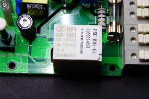
First step was to redo all the work I had already done when I started with these remote. It worked fine with Arduino but not with the Sonoff until I realize the 433MHz receiver I was using required 5V to operate. Mmm… No worries, even thou the ESP8266 works at 3V3 I remembered that in the schema for the Sonoff the AC/DC transformer feeds 5V to an LDO, so I could get the 5V from there.
Front view of the Sonoff board with pin descriptions
Back view of the Sonoff board with pin descriptions
Second problem was where to plug it. The answer was the line of holes where the RF module is in the Sonoff RF. Only two of those pins are tied to the ESP8266, the closest to the relay are GND and 3V3. Could I be so lucky? NO. The receiver I have (the standard RFLink you can find at ebay and such) has 4 pins: GND, DATA, DATA and VCC. Besides, the module just did not fit so close to the relay so the first pin would go in the second hole (the 3V3 hole)… OK, time for the X-Acto knife, the iron and the dremel.
The RF receiver. I removed the black plastic around the pins to solder it closer to the board, otherwise it won’t fit in the case.
First I cut the traces leading to the 3V3 pin in the RF row of holes (that’s the second hole counting from the relay). There are surface traces on both sides of the board, so I had to cut both and then bridge them together again. Then I soldered the module in the 2nd, 3rd, 4th and 5th holes. I brought GND from the 1st to the 2nd hole, I then connected the DATA pin to the GPIO14 in the perpendicular row of pins through a voltage divider to ground to lower the 5V from the module to 3V3. A 10K and 20K 0805 SMD resistors do the job, but it was really hard to solder them between the pins… Next I soldered the VCC pin of the RF module to a spot in the board I checked was connected to the 5V rail.
Check the cut just by the LDO, there is another one in the same spot in the other side of the board. But cutting those traces removes power from the ESP8266 so I had to wire it again (it’s the white wire in the right). The other white wire powers the RF module with 5V. You can also see the GND bridge between pins 1 and 2 in the top row and the voltage divider from the DATA line to the GPIO14 and GND pins.
I also had to dremel a bit the case to allow some room for the module
Done. A bit of a mess but it worked!
“My” Sonoff RF
But the maximum distance from the remote to the module was something in the 20cm… until I soldered a 17.3cm wire to the antena hole in the RF module (that 1/4 of a 433MHz wavelength). Now I can be 10 meters away, even with a wall in between and I can still switch it on. And before you say anything: yes, range should be better for a 433MHz module but it’s fine, after all I can still switch it on/off from Australia via the Internet.
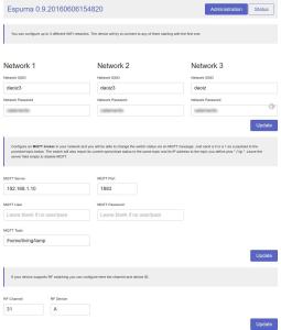
ESPurna Firmware
There are some fine control firmwares out there for the ESP8266. Some of them are generic and let you manage the pins one by one, some of them are more specific for “smart switches” based on the Espressif chip. Most of them have MQTT and Web configuration. Some are small enough so you can flash them Over-the-Air to the 1Mbyte Sonoff. None of them (at least I haven’t found any) have RF capabilities.
So I decided to build my own. After all that’s fun. I’ve named it ESPurna (“espurna” means “spark” in catalan) and it features:
WebServer for configuration and simple relay toggle
Final step is to “wire” it all together. The Sonoff with the ESPurna firmware connects to my home WiFi and subscribes to a certain MQTT topic. Upon reception it switches on or off the relay depending on the message payload (0 for OFF, 1 for ON, 2 for TOGGLE). Whenever the relay state is changed it also publishes the new state to the same topic (there is code to avoid recursion). So if you change it manually pressing the button or with the RF remote you still have a record of that.
In my home server I have Node-RED running. A few months ago I switched from a bunch of python scripts to Node-RED for message persistence (in MySQL), notifications and to push data to some online services like Xively or TheThings.io.
With MQTT and Node-RED working adding support for Blynk was a piece of cake. In 10 minutes I had a simple dashboard in my phone from where I could switch the lights on and off. In fact, I’ve spent way more time moving around controls in the dashboard canvas trying to make it look cool (I failed).
My blynk configuration in Node-RED. So easy!
You know something is well designed when things fit in like magic.
Wow. I feel like I should explain many more things about this project, but there will be a follow up so stay tuned
Have you ever forgotten your wet clothing inside the washer for a whole day? I have. Even for two days. They smell. You have to wash them again and you know you might end up forgetting about them again!
Actually that is happening to me since me moved to an old house in a town north of Barcelona. Instead of having the washer in the kitchen, like we used to, now we have it in the cellar, in a place I don’t normally pass by to notice the laundry is done.
So I started thinking about monitoring the washer to get notifications when the laundry is done. And since I was at the same time playing with ITead’s Sonoffs, which has an AC/DC transformer and a powerful controller with wifi, it looked like a nice project to put together.
EXTREME CAUTION: live mains are very dangerous. Don’t work with them unless you know what you are doing and what the consequences might be.
Wiring the ADC pin
The Sonoff does not bring out the ADC pin on then ESP8266EX. Some Sonoff TH versions do bring out GPIO14 and latest Sonoff TH 10A/16A probably do the same through a jack interface. But that’s not the case for TOUT aka ADC pin.
No problem, follow me: grab the iron with a narrow tip, a short thin cable and a magnifier, because you are going to need it. If you are not really good at soldering (and I’m not) you can still do it, but you will have to check and double check for bridges between the ADC pin and its neighbours. The ADC pin is the 6th in the left side of the chip (with the dot on the top left corner).
First solder a 3 pin header on the unpopulated holes for the RF module. If you use the first 3 counting from the relay you will already have GND and 3V3 on the first two, so you just need to connect the ADC pin in the Espressif chip to the third header. Take your time, do not apply heat for more than a second and leave it cool before doing it again. Check with your continuity tester after and prepare a simple gig to test your hack: a 10k potentiometer with a 20k resistor to build a voltage divider will do.
Update:
Don’t work with the board connected to mains! Again: Don’t work with the board connected to mains! After testing for shorts and continuity hot glue everything to prevent the cable from comming loose and create a potentially fatal short between mains.
That was tricky! Bringing out the ADC GPIO in the ES8266EX to a 3 pin header using the unpopulated RF header of the Sonoff…
Sensor board
Now that I had the ADC pin I prepared a simple stripboard with a current sensor and a simple voltage bias circuit. The current sensor I use is a chep (and not very accurate) Talema ASM-010. It outputs a small voltage proportional to the current flowing through the hole. According to the charts in the datasheet the ratio is about 300A per 1V. That’s a very poor value, and even thou I could pass the cable twice, reducing the ratio to 150A per V the YHDC SCT-013-030, a very common non invasive current, has a ratio of 30A per 1V, 5 times more accurate. But I just need to know whether there is current flowing or not.
The board has two resistors (nominal 10k and 56k) to build a voltage divider to bias the output voltage by 0.5V so the ADC will always read positive values, and a 10uF capacitor to soften signal.
The sensor board with one of the live cables doing two turns inside the coil. There are also two resistors to bias the voltage and a capacitor.
The Sonoff and the sensor board inside the enclosure.
Adapting the EmonLib
The EmonLib is the unofficial standard library to monitor current on an Arduino and alikes. But it doesn’t support ESP8266 based boards yet. Current issues are:
It only supports 10 bit ADCs (ESP8266 ADC is 10bits too, but it only has one analog pin, so chances are you will use an external ADC chip in some projects, like de 16bits ADS1115)
Voltage reference calculation doesn’t take into account non-atmel chips (the ESP8266 ADC is 1V referenced)
Analog reading is hardcoded in the library, again, what if you are using and external chip with I2C communication?
The usual approach is to include parts of the library code into your code and monitor analog pin 0. You could also use and external ADS1115 like Tisham Daar does.
This is not the first project I use current monitoring on a ESP8266, so I decided to wrap all the functionality I wanted in a proper library. And so EmonLiteESP was born. As the name says it’s a lite version of the EmonLib, since it only supports current monitoring at the time (only apparent power). But truth is that naming it after the EmonLib could be misleading since it is not API compatible (and maybe I’m violating some trade mark, didn’t check that).
The library main features are:
Customizable ADC bit count
Customizable ADC voltage reference
Read ADC values via callbacks
And its easy to use:
#include "EmonLiteESP.h"

EmonLiteESP power;

unsigned int adcBits = 10; // ADC bit resoltion (normally 10)
double referenceVoltage = 1.0; // 1.0V for a bare ESP8266 chip
double currentRatio = 30; // 30A 1V for a YHDC SCT-013-030
double mainsVoltage = 230.0 // EU standard
unsigned int samples = 1000; // 1000 samples each time we measure current

unsigned int currentCallback() {
   return analogRead(0);
}

void setup() {
   Serial.begin(115200);
   power.initCurrent(currentCallback, adcBits, referenceVoltage, currentRatio);
}

void loop() {
  double current = power.getCurrent(samples);
  Serial.print(F("Power now: "));
  Serial.print(int(current * mainsVoltage));
  Serial.println(F("W"));
  delay(5000);
}
Now that…
Some time ago, at a previous job, our CTO was very concerned about unnecessary code. He had a list of anti-patterns to identify bad practices when developing a new feature. The YANGNI (You Are Not Gonna Need It, meaning just code what you are going to use now) was his favourite one. Another favourite was the YAQUE (spanish for “Now that…”). Now that we are touching this code, why don’t we add this cool feature?
So breaking the YAQUE rule I added a DHT22 sensor because I could, and because we have moisture related problems in the cellar. The sensor is connected to the GPIO14 pin already available in the Sonoff board. I soldered a 10K SMD0805 resistor between the left-most 2 pins of the DHT22 (VCC and DATA) and drilled a hole in the case to place the sensor outside the box.
Another improvement was to add a case mounted momentary button on the enclosure, soldered to the onboard button, so I can manually switch the relay ON and OFF.
A wired Sonoff board with connections to the current sensor board, to the DHT22 temperature and humidity sensor and to the case mounted button.
The final project box
I have included all these features in my last ESPurna firmware version. Please check it out at espurna bitbucket repository.
Analyzing the data
So the goal of this project was to get a notification when my laundry is done. You don’t really need an accurate power measurement for that, only monitoring if there is current flowing or not and keeping track on how long has the washer been “quiet”.
First step is to see how the washer power profile looks like. It will probably depend on the washing program you are using but for the one we normally use for day-by-day laundry it looks like this:
So you can see the washer has been working for 27 minutes (from 11:27 to 11:54) with several quiet windows of no more than 2 minutes each. Please note this measurements have been taken every minute averaging 6 readings every 10 seconds. For this program it might be enough to check whether the washer has been quiet for the last, say, five minutes after seeing activity and then emit the notification.
Node-RED driven notifications
Final step is to set a notification when the laundry is done. I’ve been using Node-RED for some time now and I like having everything in one place in a flexible and structured way: notifications, database persistence, cloud service connections (xively, blynk, thethings.io, thigspeak…), schedulers,…
Now that I have an MQTT topic with the washer power consumption is pretty easy to write a javascript function that monitors it and sends a notification when the washer has been idle for five minutes after some significant activity. To implement that I built a 5 positions ring that stores whether there has been activity or not for the last 5 minutes or last 5 messages. It sets a flag when at least 3 of those messages contain non-zero values (that’s a significat activity). After that, when the buffer empties (5 minutes without activity) it sends the notification and clears the flag.
I’m sure the code will be much more clear than my explanation:
// Configuration
const WASHER_BUFFER = 5;

// Get current state
var washer_flag = flow.get('washer_flag') || 0;
var washer_sum = flow.get('washer_sum') || 0;
var washer_store = flow.get('washer_store') || Array(WASHER_BUFFER);
var washer_pointer = flow.get('washer_pointer') || 0;

// Update state
var current = parseInt(msg.payload) < 100 ? 0 : 1;
washer_sum = washer_sum - washer_store[washer_pointer] + current;
if (washer_sum < 0) washer_sum = 0;
washer_store[washer_pointer] = current;
washer_pointer = (washer_pointer + 1) % WASHER_BUFFER;
if (washer_sum > 2) washer_flag = 1;

node.status({
    fill: (washer_sum === 0) ? "red" : "green",
    shape: "dot",
    text: "Washer machine state: " + (washer_sum === 0 ? "idle" : "working")
});

// Notifications
if ((washer_flag === 1) && (washer_sum === 0)) {
    washer_flag = 0;
    msg.topic = "Washer";
    msg.payload = "Your laundry is done!!";
    msg.trigger = {
        'topic': '/trigger/washer/done',
        'payload': 1
    };
} else {
    msg = null;
}

// Store state
flow.set('washer_flag', washer_flag);
flow.set('washer_sum', washer_sum);
flow.set('washer_store', washer_store);
flow.set('washer_pointer', washer_pointer);

return msg;
The message is then passed to a subflow that sends it to Pushover service and also publishes it to the local MQTT broker.
Firmware over-the-air is great. It makes you shiver whenever you throw an update to one of your devices. The ArduinoOTA library for ESP8266 is so easy to use it’s almost magic. But once you have several devices deployed you start to think one step further.
Here I’m going to talk about two different options: writing an automated deployment script that performs OTA updates or giving your device the ability to call home querying for new updates, downloading them and flash itself into the latest version available.
A deployment script
First option is to have an automated deployment script. Something that grabs the latest stable version of your code and throws one update over the air for each device, probably providing specific options for each device, like “add DHT22 support”.
Since I use platformIO I can create custom environments for each device, like this:
It defines the platform, board, build flags or OTA parameters. But as you can see you have to declare the IP of the device. That is troublesome. Normally your device will keep its IP for a long time as long as it keeps connected or if your router leasing time is long enough for the device to claim its previous IP if it doesn’t. But what if it changes? And it will. Eventually.
You might have notice a non standard parameter in the previous environment definition: topic. A simple bash script can use this information to query your local MQTT broker for the latest (the retained) value of this topic and use this value as the IP for over-the air flashing. This is the script:
#!/bin/bash

MQTT_HOST=192.168.1.10

function help() {
  echo "Syntax: $0 "
  devices
}

function devices() {
  echo "Defined devices:"
  cat platformio.ini | grep 'device]' | sed 's/\[env:/ - /g' | sed 's/\-device]//g'
}

function valid_ip() {
  local stat=0
  rx='([1-9]?[0-9]|1[0-9]{2}|2[0-4][0-9]|25[0-5])'
  if [[ $ip =~ ^$rx\.$rx\.$rx\.$rx$ ]]; then
    stat=1
  fi
  return $stat
}

# Check arguments
if [ "$#" -ne 1 ]; then
  help
  exit 1
fi
device=$1-device

# Get IP
topic=`cat platformio.ini | grep $device -A 10 | grep "topic" | cut -d' ' -f3`
if [ "$topic" == "" ]; then
  echo "Unknown device $device or topic not defined"
  devices
  exit 2
fi

ip=`mosquitto_sub -t $topic -h $MQTT_HOST -N -C 1`
if valid_ip $ip; then
  echo "Could not get a valid IP from MQTT broker"
  exit 3
fi

platformio run -vv -e $device --target upload --upload-port $ip
Now you just have to declare the environment for each device in the platformio.ini file and call the script once for each device.
This option is great. If you write your code right you can create lightweight binaries targeted for each device from the same code base. The deploy script must check if the update has been successful by monitoring the update output. But I’d also provide a way to listen to client’s “hello” messages after reboot. These messages should contain the current versions for the firmware and the file system.
This works fine for 10, maybe 15 devices. That is for a home or small office. Another requirement is that you must be in the same network the device is. What if you have to manage some tens or hundreds of devices? What if they are in different networks, buildings, towns, countries?! You will need some kind if unattended pull update process, something Windows has been criticised for a long time but, hey, we are talking about small, simple, one-task-oriented, unattended devices.
Automatic Over-The-Air Pull Updates
I’ve been testing this automatic over the air update process based on the official ESP8266httpUpdate library. The library handles the download and flashes the binary and it supports both firmware and file system binaries. There is even an example that can be used as a starting point.
I’ve added a way to discover available updates and wrapped it up in the same fashion the ArduinoOTA library does, providing a callback method to display debug messages or perform in-the-middle tasks.
This first revision of the protocol is very simple. The client device does a GET request to a custom URL specifying its DEVICE and firmware VERSION this way:
GET http://myNofussServerURL/DEVICE/VERSION
For instance:
GET http://192.168.1.10/nofuss/SONOFF/0.1.0
The response is a JSON object. If there are no updates available it will be empty (that is: ‘{}’). Otherwise it will contain info about where to find the new firmware binaries:
Binaries URLs (for the firmware and the SPIFFS file system) are relative to the server URL, so following with the example, the device will first download the SPIFFS binary from:
Next you will have to configure your webserver to configure the URLs. If you are using Apache then all you have to do is create a new service pointing to the server/public folder. The .htaccess file there will take care of the rest. If you are using Nginx the create a new site file like this one:
server {
    listen 80 default_server;
    server_name nofuss.local;
    root /<path_to_project>/server/public/;
    try_files $uri $uri/ /index.php?$query_string;
    index index.php;
    include global/php5-fpm.conf;
}
Make sure the server has permissions to write on the logs folder, the server will store there a log with information on the devices that queried for updates, the version they are reporting and the answer they received.
Versions
The versions info is stored in the data/versions.json file. This file contains an array of objects with info about version matching and firmware files. Version matching is always “more or equal” for minimum version number and “less or equal” for maximum version number. An asterisk (*) means “any”. Device matching is “equals”.
The target key contains info about version number for the new firmware and paths to the firmware files relative to the public folder. If there is no binary for “firmware” or “spiffs” keys, just leave it empty.
The client library depends on Benoit Blanchon’s ArduinoJson library. In the example it is set as a dependency in the platformio.ini file, so if you use PlatformIO it will automatically download.
To use it you only have to configure the global NoFUSSClient object with proper server URL, device name and version in your setup:
And then call every so often NoFUSSClient.handle() to check for updates. You can also monitor the update flow providing a callback function to the onMessage method. Check the basic.cpp example for a real usage.
Wrap up
I wanted this library it to be easy to use and lightweight so I can still do OTA on 1Mb devices. The wrapper itself adds very little to the binary size but the JSON support certainty plays against this. Will give a try to plain text output.
As I said the code is free source and available at the NoFUSS repository at bitbucket. The project is currently in beta status, it works but I’m not 100% confident and I have doubts about the API of the service so any suggestions will be welcome.
Some 3 years ago I started building my own wireless sensor network at home. The technology I used at the moment has proven to be the right choice, mostly because it is flexible and modular.
MQTT is the keystone of the network. The publisher-subscriber pattern gives the flexibility to work on small, replaceable, simple components that can be attached or detached from the network at any moment. Over this time is has gone through some changes, like switching from a series of python daemons to Node-RED to manage persistence, notifications and reporting to several “cloud” services.
But MQTT talks TCP, which means you need some kind of translators for other “languages”. The picture below is from one of my firsts posts about my Home Monitoring System, and it shows some components I had working at the time.
All those gears in the image are those translators, sometimes called drivers, sometimes bridges, sometimes gateways. Most of them have been replaced by Node-RED nodes. But not all of them. This is the story of one of those gateways.
Moving from XBee to Monteino
I want you to focus on the “Xbee MQTT Client” in the previous image. XBees are fairly expensive, hard to configure but also pretty powerful and full featured. I could deploy battery powered end devices that run for months from a coin cell like my door sensor or backed by a solar panel like in my weatherstation.
A year ago I started playing with LowPowerLab’s Monteinos as a replacement for the XBee network. A Monteino is an ATMega328 with the Arduino bootloader and HopeRF RFM69 radio on board, everything running at 16MHz and 3.3V. It is a truly low power device and the guy behind LowPowerLab, Felix Rusu, along with the Monteino community have put together an awesome set of libraries to use them. RFM69 use the ISM 868MHz band (here in Europe) with a longer range than the 2.4GHz XBees (although the later have mesh capabilities).
But Monteinos, just like XBees, do not speak TCP. They speak their own language over a FSK modulated radio signal at 868MHz. So you need a gateway to translate messages back and forth the two networks. That’s it, an RFM69 to MQTT bridge.
My first approach a year ago was to copy the XBee gateway idea I was using at the time, basically an XBee in coordinator mode listening to packets from the nodes and forwarding them over serial port to a computer running a python daemon with the python-xbee library to decode API frames and map them to MQTT topics using the Mosquitto python library (before it was donated to the Eclipse Paho project). So I wrote a simple program adapted from Felix Rusu’s gateway.ino example running in a Monteino with an FTDI adapter (yes, there is a MonteinoUSB but I don’t have it) that passes messages over serial port to the computer that translates them to MQTT messages.
Standalone gateway
A Monteino with an FTDI adapter, passing data over serial in a custom protocol to a python script to translate them to MQTT… and back. I was not satisfied with the solution and I never finished the migration from XBee to Monteino.
But now I’ve done another step in what I feel like is a good solution. A standalone ESP8266-based gateway with an RFM69CW radio module on board. I’m not going to say this is the final solution, still have some doubts about it but I like it because it’s a microcontroller based solution, that does just that, bridging two different networks, without help from any other component.
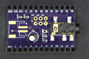
RFM69GW board v0.1
RFM69GW v0.3 – top view: fixed ESP12 footprint error, improved silkscreen labels and bigger holes
RFM69GW v0.3 – bottom view
For the first version I had to take some decisions:
Through hole components except for the radio modules, the AMS1117 and the buttons. I wanted it to be easy to solder.
Also I used RFM69CW footprint because it’s pin-compatible with the RFM12b, so in theory (I have not test it), you could make it work with old Monteinos or JeeNodes.
Non FTDI-like programming header. This was a hard decision but I had not very much free room and decided to bring out a GPIO instead, in case I wanted to attach some digital one-wire sensor.
Version 0.1 of the board has some errors, but still it’s usable. There was a fail in the ESP12 footprint I used, GPIO4 and GPIO5 were swapped. As a consequence DIO0 in the RFM69 module is tied to GPIO5 instead, nothing that could not be fixed changing a value in code. Also somehow I drew M2 holes in the board instead of M3 and the programming header is too close to the bottom-right hole so I have problems with common standoffs. And finally, there are problems with some of the silkscreen labels being too small (the button labels for instance) or missing (like the component values). This error has no impact on the functionality but I made it also on two other designs I sent to fab at the same time (ouch!).
Features
Testing the gateway. The monteino in the picture has Rusu’s example gateway firmware, so I could check that nodes were sending well formed messages.
The project firmware packs some interesting features, IMHO. Let me summarize them first:
Up to 3 configurable WIFI networks
Over-The-Air firmware update (OTA)
MQTT support, off course
Dynamically map nodes/keys and MQTT topics
WebServer for configuration using the great PureCSS framework
Persistent configuration across reboots using Embedis
Optional default topic for non mapped nodes/keys.
Configurable IP and Heartbeat topics
Visual status of the received messages via the ESP12 LED
Topic mapping
As I explained in another post about MQTT topic naming I think the gateway should be the only responsible for translating messages from one network to another, and this means it has to have the logic to publish messages to the right MQTT topic, for instance. So I wanted to be able to dynamically define a map between nodes, variables and topics.
Web configuration page for the node-to-mqtt map
The gateway expects to receive messages with the key, the value and optionally the packetID (from the sender point of view) separated by colons (i.e. “BAT:2890:34″). This format is not the best in terms of size, but it’s compatible with Rusu’s MotionMote, for instance, and I had already used it in my XBee network. You can then map the combination of nodeID (available in the header of the message) and key to an MQTT topic.
You can also define a default topic that will be used when no match has been found in the map. The default topic can contain {nodeid} and {key} as placeholders to create custom on-the-fly MQTT topics.
Persistence
The other great feature is the configuration module. Just one word: Embedis. You have to use this library by PatternAgents. It’s basically a key-value database for microcontrollers that supports different platforms (including Arduino for AVRs and ESP8266) and different storage like SPI or I2C memories, EEPROM or emulated EEPROM like in the ESP8266. It’s easy to use, robust and powerful, and comes with console management with customizable commands as bonus feature.
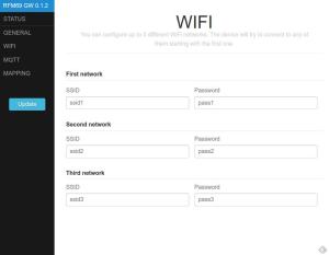
Web configuration portal
Another aspect of previous projects I wanted to improve is the web configuration portal. I wanted to give PureCSS by Yahoo a try and it worked great, with jQuery as client language and ArduinoJson and Embedis in the backend. The layout is simple but looks great both on my laptop and on my phone and it’s much more usable than my previous efforts.
The JustWifi library supports up to 3 different networks. If it fails to connect to one of them it will try the next one.
Wifi & Radio management
Also, I have worked in encapsulating wifi and rmf69 functionality in two classes. The first one, JustWifi, is inspired by WifiManager but it just handles wifi connection (hence the name) ripping off all the webserver and DNS stuff. The second one, RFM69Manager, encapsulates the setup and receiving code and outputs a custom packet to the provided callback with all the useful information for a message (nodeID, key, value, packetID and rssi). It also wraps the send method to format a compatible message (“key:value:packetID”).
RFM69 and ESP8266
The moment I read this post in the LowPowerLabs forum I decided to do this project. Felix’s library for the RFM69 was compatible with the ESP8266 almost without modification! But the comments there were a bit confusing. So this is how I made it work:
Modify the SPIFlash.cpp file to check SPCR & SPSR before using. My solution is to wrap them between #if clauses to avoid compile errors if not defined, which happens in ESP8266. I’ve forked Felix’s library. Here you have the diff for the changes I made.
Initialize the RFM69_ATC object (or the RFM69, whichever you use) passing the SS and interrupt pins.
RFM69_ATC radio = RFM69_ATC(SPI_CS, IRQ_PIN, false, IRQ_NUM);
I use this code in my RFM69Manager library. With these 2 changes it just works. No more changes needed.
This is what the console output looks like. Messages are from a node that’s continuously sending the same payload. The node was powered after the gateway came to life, that’s why the first packetID is 1. You can also see how the RSSI value goes down. This is due to the Auto Transmission Control in the RFM69_ATC library that’s set to a minimum of -70. The transmitter will keep on lowering the output power to match this RSSI value, saving power and reducing radio pollution. Key “BAT” for node ID 10 is mapped to “/home/frontdoor/battery” topic (see screen capture above).
Funny enough, while waiting for the boards to arrive from a chinese factory, a couple of very similar projects have come to public attention, the Ebulobo by James Coxon and the Espism by Johan Kanflo.
Both boards are smaller than mine, basically because they place each module on one side of the PCB. They have both chosen to use an USB-A socket to power the board resembling an USB stick, while I use a 2.1mm barrel jack. The Ebulobo board has an SMA connector to plug an antenna, but the Espism uses a pigtail wire as antenna. My board has both options.
James’ Ebulobo uses a header to program it, very much like I do, but without power line (the board has to be plugged to a powered USB port) and instead of having a FLASH button on-board to pull GPIO0 down on boot, it brings out the GPIO0 in the header and you have to use a jumper to tie it to ground. Johan uses a custom programming connector (the Esprog) to flash the firmware on the Espism. This way he reduces board size but the payload is… that you need a custom programming connector.
Both projects have open sourced their schematics, board and code, so they are great projects to learn from. I like their form factor, not sure about the USB connector, not even if there was an FTDI chip and circuitry to program it like you would do to a NodeMCU. OTA is a better option in any case. If the reason is the ubiquity of a power supply connector a microUSB socket would be a better option.
Improvements
I’m just starting to deploy devices using this gateway. I guess I will find things to improve on the way. Right now, the main improvement I have in mind is to support sending messages from MQTT to a remote actuator with an RFM69 radio. Right now the gateway is only one-direction.
The problems I have identified in the board layout are fixed with version 0.3 in the repository, but since the board is fully usable I don’t plan to send it to fab. Yet.
I’m happy with the firmware, it’s a huge improvement from what I had been doing lately and I plan to migrate other projects like my Espurna Smart Socket firmware to use PureCSS and Embedis.
Again, any comment will be welcome.
Tinker and have fun!
Some weeks ago I received a parcel from Itead. Previously, I had written about the Sonoff and they were kind enough to send me two more of their home automation products for me to review: the S20 Smart Socket I wrote about two weeks ago and the Slampher.
The Slampher comes in a simple cardboard box with no documentation at all… just visit their wiki!
The Slampher is kind of a Sonoff RF that sits before any light bulb with an E27 screw. As you can see in the header pic of this post it adds quite some length to the group. It’s a bit bulky and might not fit in every lamp. Off course the board layout is different from the Sonoff and it uses a JST131U-800D 1A triac instead of a relay to switch the bulb. Aside from that they are equivalent.
The JST131U-800D triac in a TO-92 package is placed in the the center of the board
There are a number of reviews of the Slampher that focus in the basic usage or that go more in depth tearing it apart or flashing a custom firmware. As you can guess, I’m more interested in the later. I already exposed my reasons in my post about the S20 Smart Socket and this week it has become more apparent as a report from Bitdefender has uncovered a bug on a commercially available smart socket that would allow attackers to create a malicious botnet. An army of owned sockets!
We are only a few days away from the arrival of the ESP32 and the ESP6288 is still one of the kings of the IoT block, and a really a successful one. Itead choice of using Espressif chips on their home automation line of products make them a hackers dream.
There are a few firmwares available that will work on the Slampher, including my Espurna Firmware. Most of them have MQTT support and a web configuration portal. Some, like the Espurna, are light enough to support OTA with the 1Mb flash memory that the Sonoff or the Slampher have.
Flashing the Slampher
The Slampher and the Sonoff RF both have a 8bit EFM8BB10F2G-A-QFN20 microcontroller (from the EFM8 Busy Bee family) by Silabs that listens to the radio module messages and handles the on-board button. That button is tied to GPIO0 in the Sonoff TH or the S20 Smart Socket and it can be used to enter into flash mode upon boot. Same things does not happen on the Slampher.
The EFM8BB1 is the little 3x3mm chip at the top right of the image, just by the testing pads.
The EFM8BB1 intercepts the button events so it can enter into “pairing mode” when the user double-clicks the button. In pairing mode it listens and stores a new radio code that will become the code to toggle on and off the switch from then on. But the curious thing is that if there is a single click event it just pulls down GPIO0 in the ESP8266 like the the button does in the non-RF versions. So Sonoff firmwares will work just the same except for:
You cannot use the button to enter flash mode in the ESP8266 (since it’s a user firmware event that pulls GPIO0 down and no user firmware is running at boot time).
You can’t use double click events on your firmware because these are intercepted by the EFM8BB1, unless they are more than about half a second away from each other.
You can’t use long click events since the EFM8BB1 pulls GPIO0 down only on button release for about 125ms.
Issues #2 and #3 you will have to live with them. My Espurna firmware uses double click and long click events to enter AP mode and to reset the board respectively. That will not work on the Slampher. I could extend the double click interval in the DebounceEvent library from 500ms to 1000ms, but it won’t be very user friendly.
Issue #1 has different solutions. Scargill suggests to move resistor R21 to R20, so the button is now attached to ESP8266 GPIO0 (check the schematic at Itead wiki). Problem is that you lose the ability to pair your remote. Off course you could pair it first and then move the resistor but chances are that in the long run you will need to pair it more often than flash it, because you have OTA.
So my solution is to momentarily shortcut to ground the unpopulated pad of R20 that goes to GPIO0 and power the device at the same time. It’s not easy, you will need some practice and you will probably have to do it more than once. But at the end you will have a customized Slampher with fully working RF support.
Short to ground the R20 pad that goes to the ESP8266 while powering the board to enter flash mode
Off course I’m assuming you have a stable OTA-able firmware and that you have a testing platform (I have a Sonoff just for that). Also, you can add a new button between the pad and GND to flash the device in a more comfortable way.
The Slampher has a 4 pins header that brings out everything you need to flash it (except for GPIO0), counting from the little white mark onwards: VCC, RX, TX and GND. You just need to wire your favourite USB to UART board (an FTDI-like) and you are ready to go. Just remember: the ESP8266 requires 3V3, not 5V! And connect TX to your programmer RX and RX to TX. Then you will need to handle the board with care with another ground jumper wire touching the R20 right pad (check the images) while you disconnect and connect you FTDI board or the VCC cable.
Somewhat hard to see but here you have my flashing set up… notice the additional black wire in the breadboard I use to pull down GPIO0 on boot
Radio codes
The radio receiver chip is a SYN470R by Synoxo in a 16 pin SOP package. This is a ASK/OOK RF transparent link (an “antenna-in to data-out” as the manufacturer says). It needs a microncontroller to act as a logic decoder. You can configure the bandwidth and it has a WAKEUP pin you can use to wake up your controller when there is a radio signal.
First I tried to pair it with my Avidsen remote without success. Then I used another remote I have for Noru radio sockets and it worked! Kind of… The red LED in the radio modules blinked while pairing it but not all the buttons worked. Only ON1, OFF2, OFF3 and 8H buttons on my Noru remote actually work with the Slampher. Weird.
The Noru remote is the one on the left
So I reviewed my own post about decoding radio signals but instead of using my Bus Pirate I give it a try to the RCSwitch library first, using the basic receiver example and adding some code to output “normalized” data strings, I started decoding the 4 buttons of the remote Itead is selling. This is the code I used:
The output of the 4 buttons from the Itead remote is:
Button
Value
Binary
Tetrabits
A
11708433
101100101010100000010001
X10XXXX00F0F
B
11708434
101100101010100000010010
X10XXXX00F0X
C
11708436
101100101010100000010100
X10XXXX00FF0
D
11708440
101100101010100000011000
X10XXXX00FX0
As you can see they are 24 bit messages where the first 20 are the same for the 4 buttons and then there is only one bit set for the remaining 4 bits. The 4 buttons in the Noru remote that work have only 1 bit set in the last 4. That’s why the remote Itead sells has only 4 buttons. I still don’t know if I can use Itead’s remote with the Noru sockets since I never managed to know the relation between button codes (between ON and OFF buttons that control the same socket). But they don’t look compatible…
Note: one funny thing is that there is another EFM8BB1 microcontroller on the radio module. What? Maybe the radio decoding is done in this second chip while the one in the Slampher board is just responsible for the button and the GPIO0?
Wrapping up
The Slampher might be a bit bulky and it won’t fit in all the lamps (it does protrude from the livingroom lamp cover at home) but it’s a fine device for home automation. My criticism to the eWeLink app and my concerns about really owning the device still stand. But I will no doubt tell you: go buy one, flash it with your own firmware and enjoy.
Some days ago I posted about the RFM69 to MQTT gateway based on the ESP8266 I am working on. Over these days I’ve been fine tuning the gateway at the same time I was migrating one of my home sensors to Monteino: the Door Monitor. The previous version was based on an XBee radio and has been on duty for almost 3 years and a half. Real life battery time has been around 3 months for a CR2032 coin cell, which is not bad at all, but still…
Aside from using a Monteino and a RFM69 868MHz radio instead of the XBee, I have reduced the components list by moving hardware logic to software logic. This means using sleeping capabilities of both the ATMega328 and the RFM69 and coding in a clever way to reduce awake time.
Hardware
As I said, hardware is much simpler in this second version of the door monitor, you can check here both “generations” side by side:
Two generations
This second generation is basically a Monteino with a RFM69W on board, a voltage divider to monitor battery, a reed switch with a pull-up and a screw terminal to connect a battery. That’s it. The reasons to move to a Monteino were mainly 3:
Better customization. XBees are programmable, but really, who does that? So here you have a good-old Arduino with enough processing power to use almost any sensor out there.
Longer battery life. You have more options from code, like putting the radio, the flash chip and the microcontroller itself to sleep. Besides I wanted to include a beefier battery solution, like 3-AAA batteries with >1000mAh.
Easier to use. I had my share of the X-CTU software over Wine.
Fritzing might not be your cup of tea… but it helps when designing on a strip board… I only wish you could apply transparency to the components, so you could see the cut traces under the Moteino Monteino…
There are a few things to note hardware-wise. First the battery monitor has been designed after John k2ox post in the LowPowerLab forum. The voltage divider consists on a 470k and a 1M resistors. The downstream resistor is not tied to GND but to digital pin 12. When this pin is in high impedance mode the circuitry is disabled and no power is wasted. To measure voltage you first have to set it to OUTPUT and then LOW, do an analogRead in A1 and put D12 back to INPUT.
The voltage divider resistors under the Monteino
Second the pullup resistor in the reed switch was a late addition to check weather there was a drop in power consumption compared to the internal pullup. But there wasn’t. I’m a bit surprised by this fact but I couldn’t get a different result. To see how I did the measurement look for the Power section below.
Also, this might not look important but it could save you some (little) money and a lot of headache. Those reed switches are reaaaally fragile. The critical moment is when you have to bend its legs. After breaking some of them, I always use a small plier (a needle nose one) to hold the leg just before the bending point, so the capsule is protected in one side of the plier and I gently bend the other end. Check the picture:
Bend the reed switch legs using a plier to protect the glass capsule
And finally, test what is the best position for the reed switch and the magnet. For round neodinium magnets the switch should be perpendicular to the plane of the magnet (check the header image in this post) and this one:
I wanted the reed switch to be in the back of the board so it will be closer to the magnet… but careful with shorts…
Firmware
The code is quite simple, it relies on Felix Rusu and Thomas Studwell RFM69_ATC and RocketScream Low-Power libraries. The reed switch is tied to an interrupt pin that awakes the Monteino whenever it changes it’s state. Then the code debounces the signal and checks if the value has changed. I started with a 25ms debounce time and later I checked with my DSO Nano that 5ms is more than enough. Signal and messaging looks a lot more reliable than with the XBee, where I had bounces and ghost signals (a door open and closed trigger two messages and seconds after, two more messages).
This is the loop code responsible for the sleeping and awaking of the microcontroller:
void loop() {

    // We got here for three possible reasons:
    // - it's the first time (so we report status and battery)
    // - after 4*15 seconds (we report status and maybe battery)
    // - after an event (same)
    send();

    // Sleep loop
    // 15 times 4 seconds equals 1 minute,
    // but in real life messages are received every 77 seconds
    // with this set up, so I'm using 13 here instead...
    for (byte i = 0; i < 13; i++) {

        // Sleep for 8 seconds (the maximum the WDT accepts)
        LowPower.powerDown(SLEEP_4S, ADC_OFF, BOD_OFF);

        // At this point either 4 seconds have passed or
        // an interrupt has been triggered. If the later
        // delay execution for a few milliseconds to avoid
        // bouncing signals and break
        if (flag) {
            flag = false;
            delay(DEBOUNCE_INTERVAL);
            break;
        }

        // If the former, check status and quit if it has changed
        if (status != digitalRead(REED_PIN)) break;

    }

}
The status variable holds the last status sent and acknowledged by the gateway. So if we are missing an ACK the code will try to send the same message again in four seconds. You can check the full code at my Door Monitor repository on Bitbucket.
I’m using a wrapper library (RFM69Manager) to manage the radio setup and message format. Messages are in the format:
key:value:packetID
Like in “BAT:4302:34″. The packet ID is optional but my RFM69GW uses it to check for duplicates or missing packages. It can be disabled changing the SEND_PACKET_ID value in RFM69Manager.h to 0.
Power
Power is key in this project since the sensor will be battery operated. In the first generation, with the XBee, it could work for about 3 months on a single ~300mAh CR2032 coin cell. For this second generations I wanted both more autonomy and reliability. Reliability often is a trade of with power consumption: more checks, more messages, more time awaken.
I own a poor guy’s DSO Nano oscilloscope that is good enough for a poor engineer like me, and I recently bought a uCurrent Gold from EEVblog and this is the perfect project to test it! First some static values using the multimeter.
Controller
Radio
mA
ON
ON
8.5
ON
OFF
7.5
OFF
ON
1.34
OFF
OFF
0.015
The uCurrent was set to 1mV/1mA for all the values except the last one, that required the next level of precision: 1mA/1uA. This last value is roughly twice the minimum in the Monteino specifications… don’t know why.
My power measurement set up: door sensor, battery, uCurrent and DSO Nano
The there is the transmission. Here I fastened my DSO Nano probe to the voltage output terminals in the uCurrent. And capture some nice graphics:
The different stages in the graph are described in the following table:
Stage
Description
mA
ms
1
Everybody is sleeping and suddenly… an interrupt
2
The microcontroller awakes and debounces the signal
7.2
~25
3
Radio sending
20-56
~4
4
Radio waiting for ACK
23
4.4
5
Radio off and blinking LED
7.2
5.4
6
Everybody back to sleep
You can easily spot the DEBOUNCE_INTERVAL (#2) and the NOTIFICATION_INTERVAL (#5) in the graphic. I later changed the DEBOUNCE_INTERVAL to 5ms so #2 is 5 times shorter. Also radio pulses (#3) vary depending on the transmitting power. Since Auto Transmission Control is enabled the radio will modify the transmitting power to match the given target (RSSI -70) so first bursts will use more power and it will eventually go down to a stable lower value. I have seen burst at -60 RSSI that used less power than the radio waiting for the ACK (is that even possible?). Know more about Auto Transmission Control in this post by Felix Rusu.
Normally the sender will receive an ACK in a few milliseconds (#4) and will go back to sleep. But if the gateway is too busy or the ACK gets lost the sender will retry after 40ms up to 2 more times. So the total time with the radio awaken can be 120ms + 3*4ms for each radio burst. But this rarely happens.
Two spikes 40ms apart. The gateway did not ACK on time and the node tried again.
Note that the debounce time only applies if there has been an interrupt caused by the reed switch. At home that could happen like 20 times a day. But the non-interrupt message, the heartbeat the sensor sends every minute does not have this leading time (check code above). So the normal operation would be: a heartbeat without debounce time, one single spike with a quick ACK form the gateway (averaging 4-5ms) and a nice LED blinking for 5ms at the end (off course I could get rid of this but it’s good to have some kind of visual notification).
And finally we should take into account that every 10 messages the node sends the battery reading. Let’s do the math:
Stage
mA
ms/event
events/minute
mA*ms/minute
Sending burst
56
4
1.1
246
Waiting ACK
23
5
1.1
126
Blinking LED
7.2
5
1
36
Rest of the minute
0.015
60000-4.4-5.5-5
~900
Total over a minute
~1309
This averages to 22uA (1309mA*ms/minute / 60000 ms/minute). A 1000mAh battery would last almost 46000 hours or more than 5 years!!
These calculations are assuming high power messages, 1 battery message every 10 status messages (hence the 1.1 events per minute), no interrupts (like if the whole family was on holidays) and perfect communication with the gateway (i.e. quick ACKs). Door events would add little to this and right now the gateway is responding 99% of the times within the first milliseconds… that off course could change as it has more messages to process. On the other side ATC will even improve these numbers. Time will tell. Right now numbers on paper (or blog) look gorgeous. Let’s see what numbers do real life.
The ESP8266 flash layout defines a series of blocks of memory for each “partition”. There is a block for the user code (the “sketch”), there is a block for the OTA update file, another one for the emulated EEPROM, another for the WIFI configuration and one for the File System.
This last one uses Peter Andersson’s SPIFFS (SPI Flash File System) code to store files in a similar fashion our computers do, but taking into account the special requirements of an embedded system and a flash memory chip.
This is great because we can store a whole static website there (html, css, js, images,…) and use the official WebServer library that comes with the Arduino Core for ESP8266 project to serve files and execute server side code that updates our static site via AJAX or WebSockets, for instance.
But the ESP8266 is nothing more than a (powerful) microcontroller and the WebServer library has its limitations and if you start to work on a complex website, with multiple files (stylesheets, scripts,…) it will soon fail…
Size is not that important, but the number of files is. Too many files lead to failed downloads and long rendering times…
The solution is merging. All javascript files together, all stylesheet files together. But what if you are using third party files, some of them minified? What if you want to keep them separated so you can easily swap from one component to another by just removing a line and adding a new one to your HTML file? You will need some way to process your HTML to get the scripts and stylesheets you are using, merge them and replace the references in the HTML with the unified file.
Well, that’s what most web developers do on a daily basis. They work on a development version and they “process it” to get working code (clean, minimized, renderable). They even have “watchers” that work in the background translating every modification they do on the development version in real time. To do that they use compilers (for SASS, LESS, CoffeeScript,…) and build managers. One of such build managers is Gulp.
So why not use Gulp to process our website before uploading it? Why? So let’s do it.
Installing Gulp
Gulp is actually a Node.js module which is great since Node.js is a really powerful frontend and scripting language and the building file that we will code can benefit from all that power. Installing Node.js and npm (Node.js packet manager) is out of scope here so visit Node.js download page and help yourself.
Next we will need a file to define all the module dependencies we are going to use. These modules are gulp itself and some gulp plugins that will take care of the different tasks (minimizing, injecting, cleaning,…). Lets take a look at it:
As you can see it is a JSON document with some header fields and a list of dependencies. Save it in your code folder as “package.json” and run:
npm install
It will fetch and install all those modules in a node_modules subfolder (I suggest you to add this folder to your .gitignore file). Good, let’s move ahead.
The builder script
I am going to start by showing the script:
/*

ESP8266 file system builder with PlatformIO support

Copyright (C) 2016 by Xose Pérez <xose dot perez at gmail dot com>

This program is free software: you can redistribute it and/or modify
it under the terms of the GNU General Public License as published by
the Free Software Foundation, either version 3 of the License, or
(at your option) any later version.

This program is distributed in the hope that it will be useful,
but WITHOUT ANY WARRANTY; without even the implied warranty of
MERCHANTABILITY or FITNESS FOR A PARTICULAR PURPOSE.  See the
GNU General Public License for more details.

You should have received a copy of the GNU General Public License
along with this program.  If not, see <http://www.gnu.org/licenses/>.

*/

// -----------------------------------------------------------------------------
// File system builder
// -----------------------------------------------------------------------------

const gulp = require('gulp');
const plumber = require('gulp-plumber');
const htmlmin = require('gulp-htmlmin');
const cleancss = require('gulp-clean-css');
const uglify = require('gulp-uglify');
const gzip = require('gulp-gzip');
const del = require('del');
const useref = require('gulp-useref');
const gulpif = require('gulp-if');

/* Clean destination folder */
gulp.task('clean', function() {
    return del(['data/*']);
});

/* Copy static files */
gulp.task('files', function() {
    return gulp.src([
            'html/**/*.{jpg,jpeg,png,ico,gif}',
            'html/fsversion'
        ])
        .pipe(gulp.dest('data/'));
});

/* Process HTML, CSS, JS */
gulp.task('html', function() {
    return gulp.src('html/*.html')
        .pipe(useref())
        .pipe(plumber())
        .pipe(gulpif('*.css', cleancss()))
        .pipe(gulpif('*.js', uglify()))
        .pipe(gulpif('*.html', htmlmin({
            collapseWhitespace: true,
            removeComments: true,
            minifyCSS: true,
            minifyJS: true
        })))
        .pipe(gzip())
        .pipe(gulp.dest('data'));
});

/* Build file system */
gulp.task('buildfs', ['clean', 'files', 'html']);
gulp.task('default', ['buildfs']);

// -----------------------------------------------------------------------------
// PlatformIO support
// -----------------------------------------------------------------------------

const spawn = require('child_process').spawn;
const argv = require('yargs').argv;

var platformio = function(target) {
    var args = ['run'];
    if ("e" in argv) { args.push('-e'); args.push(argv.e); }
    if ("p" in argv) { args.push('--upload-port'); args.push(argv.p); }
    if (target) { args.push('-t'); args.push(target); }
    const cmd = spawn('platformio', args);
    cmd.stdout.on('data', function(data) { console.log(data.toString().trim()); });
    cmd.stderr.on('data', function(data) { console.log(data.toString().trim()); });
}

gulp.task('uploadfs', ['buildfs'], function() { platformio('uploadfs'); });
gulp.task('upload', function() { platformio('upload'); });
gulp.task('run', function() { platformio(false); });
Let’s focus on the “File system builder”. There are 5 tasks:
clean will delete all the contents of the data folder
files will copy all images to the data folder (right now we are not processing them)
html processes the HTML files (more on this later)
buildfs calls the prior 3 to build the project
default is just a convenient task to call buildfs if no task provided.
The “html” task looks for all the *.html files in the development folder and reads them to extract references to *.js and *.css files (that’s what the “useref” plugin does). Then it generates 3 streams. The first one gets all the *.js files, merges them and minifies them (that’s what the “uglify” plugin does). Another one merges all the *.css files and minifies them (that’s what the “cleancss” plugin does). An the final one replaces all the references to the *.js and *.css files with the newly generated unified files in the HTML, and minifies it (that’s what the “htmlmin” plugin does). Finally all the resulting files get gzipped and stored in the data folder, along with all the images.
The good thing about this builder script is that you don’t have to worry about the files you add or delete from your HTML file. It will just read them and merge them in the same order they are in your code. That’s very important since often there are dependencies between files (css precedence, scripts that require jQuery to be defined,…).
Injecting code
The “useref” plugin requires some metadata in the HTML file to know where it should read the files from and inject the new code. A typical file would look like this:
As you can see the places where the plugin should read and inject new code are defined by “build” comments like this one: “<!– build:css style.css –>”. You have to define the type of files it contains (css) and the name of the output merged file (style.css). All the code from this opening comment to the “<!– endbuild –>” closing comment will be replaced by:
<link rel="stylesheet" href="style.css" />
Same for the javascript block. Now, instead of naming your file system folder “data” like the ESP8266FS documentation suggests, name it “html” (or whatever other name, but the code above requires it to be “html”). To run the builder just type from the command line in your code folder:
gulp
If everything goes OK your data folder will have 3 files at least (not counting images): index.html.gz, style.css.gz and script.js.gz.
GZIPping?
Compressing the files makes them lighter and that means you can fit more code in the same room and it will download faster too. But how does the ESP8266 handle it? Well, this code is not mine and it’s pretty standard when using the WebServer library from the Arduino Core for ESP8266, let’s see what it does:
As you can see the code gets the requested path, translates “/” to “index.html” for the home and grabs the content type from the file extension (not in the code, somewhere else, but that’s what it does). Then it checks if there is a file with the same name plus “.gz”, and if it exists that’s the file it will read. The code is completely agnostic to the contents of the file, it just streams it. But then, deep in the guts of the WebServer library we find this:
So, if the file we are reading ends with “.gz” and we are not serving a gzip file or a binary file, then we are sending something else compressed and hence we should set the Content-Encoding header to “gzip”. Voilà. Our browser will receive the file and it will know it has to decompress it prior to render it.
See the difference?
No erros, less files, less download size, waaaaay faster
What about the images?
The builder script just copies the images at the moment. There is room for improvement here: compressing them, creating sprites,…
PlatformIO
The builder script above has 3 more tasks to use them with PlatformIO. The main reason for this is that it’s convenient to run “gulp buildfs” (or “gulp” since the default tasks is “buildfs”) before uploading the file system. I’m not good at remembering such things and end up wasting time wondering why I can’t see my changes. So instead of running “gulp” and then do and “uploadfs” from platformio I just do:
gulp uploadfs -e ota -p 192.168.1.113
And my changes are built and flashed via OTA to the device at 192.168.1.113. Neat!
A few weeks ago the 4D Systems announced one of its latest products: the 4Duino-24, an Arduino compatible display module with built in 240×320 resolution TFT LCD Display with Resistive Touch and an ESP8266 ESP-06 module on board.
it looked like a great product for a home automation control panel, although the screen could have been bigger. Anyway I contacted the people at 4D Systems and they were kind enough to send me a sample to review, and hack!
I love getting packages in the mail
A conversation with the tech team
When I looked at the 4Duino-24 architecture there was something that rang a bell in my head. Well, here we have again en ESP8266 being used as a mere serial to wifi bridge.
Block diagram of the 4Duino-24 board, as you can see the main processor is an ATmega32u4, the same one in the Arduino Leonardo
The central microcontroller of the board is the Atmel ATmega32u4, the same one the Arduino Leonardo has. It’s a good 8-bit controller but nothing compared to the ESP8266 that sits a few milimeters away.
The ATmega32u4 and the ESP-06 module side by side
I quickly raised an inquiry to the 4D Systems tech team and Doff Deponio, BEng. Electronics and Communication Technical Engineer at 4D Systems, responded as follows:
Well, there are all sorts of ways to look at it.
The ESP8266 is the most powerful processor, the Picaso is second and the ATmega32U4 is the least. But the ESP8266 has limited I/O, so using it as the main processor is not ‘optimal’ as it restricts users in the I/O they can add to the configuration.
The way it is designed each processor is being used in the best way to play up eachs strengths. The ESP8266 for its ability to do WiFi, Picaso for its graphics capabilities and the ATmega32U4 for its rich hardware connectivity and available code libraries.
And it makes perfect sense. Needless to say the Arduino community is the biggest by far so placing the ATmega32u4 as the main controller makes it easier for a lot more people to use the board. The ATmega32u4 has plenty of GPIOs, digital and analog, to plug your sensors and two hardware serial ports, one of them used for the USB interface and the other one to communicate with the Picaso controller that drives the display.
Still… the ESP8266 is way more powerful. And you know what? A lot of the “available code libraries” for Arduino can be ported “as is” to the ESP8266 platorm using the Arduino Core for ESP8266 project. Including 4DSystems Picaso Serial Library for Arduino.
I want this guy to rule the board
First things first
And the first thing is to test the board with the provided example code. The board is really well documented, and everything is downloadable from the product page. The most important documents to start with are:
Also, you might want to check the 4D Workshop4 IDE that integrates code editing and tools to design the graphical interface of your application. It’s a Windows only application (me sad) and freeware except for the PRO version (trial-ware) that integrates a code-less development environment named ViSi-Genie.
This is the default screen message when the Picaso doesn’t get any instructions
If you have been reading me you would know I’m a PlatformIO fan. It freed me from the Arduino IDE and provides a whole lot of goodies and support for tons of boards and frameworks aside from Arduino ones. It’s a truly one-tool-drives-them-all!!
Flash the 4Duino-24 using PlatformIO
So my first thing was to add 4Duino support to PlatformIO. It basically comprises two steps: adding the required definitions and code the same way the Arduino IDE would do and adding an entry for the board in the Atmel AVR package for PlatformIO to know about the board.
Setting things up
The 4Duino-24 board has some specificities compared to its close cousin the Arduino Leonardo. Both have the same processor and speed but they have two small differences:
In the Leonardo PB0 and PD5 pins in the ATmega32u4 are connected to RX and TX LEDs respectively, but on the 4Duino-24 these pins are connected to the RESET lines of the ESP8266 and the PICASO controllers
The device has a different USB signature (VID and PID)
These two differences mean changes in the bootloader, the coreUSB libraries and the pin definitions file. So 4D Systems maintains a board description file for the Arduino IDE board manager that automates the process of downloading and installing custom files for the 4Duino-4D board. We will have to do the same.
The latest version of the board description file defines two packages for Arduino IDE versions 1.6.7 and 1.6.10. I downloaded the 4Duino-24 package for the Arduino IDE 1.6.10 and decompressed it. It contains several files and folders. This is what I did:
The Picaso Serial Library for Arduino is already installed (comes with the 4Duino package for the Arduino IDE) and has two example sketches to help you start with it. One of them, the “BigDemo” example, requires you to format and copy some files to the SD Card but I found that it fails compiling because the resulting image is too big
The other example, “Display_print”, works just fine. I copied the “Display_print.ino” file to the “src” folder and:
pio run -t upload
Done
Doing it upside down
Now. What if I want the ESP8266 to be my main controller? It doesn’t have direct access to the Picaso controller but I could use the ATmega32u4 as a bridge for the Picaso and also as a data provider for any sensors it may have attached. It can be tricky but it’s doable. What do I win? A lot of power and connectivity options using the ESP8266 at full potential. What do I lose? Basically display responsiveness and speed, but depending on the product it is not noticeable at all…
The ATMega32u4 as a Man-in-the-middle
The Picaso microcontroller can be controlled through serial commands and the Picaso Serial Library encapsulates these commands in a more human-friendly API. But they are just serial data flowing up and down, so it can be easily forwarded to another destination.
One of the first examples when using an Arduino is the serial passthrough sketch:
void setup() {
  Serial.begin(9600);
  Serial1.begin(9600);
}

void loop() {
  if (Serial.available()) {      // If anything comes in Serial (USB),
    Serial1.write(Serial.read());   // read it and send it out Serial1 (pins 0 & 1)
  }

  if (Serial1.available()) {     // If anything comes in Serial1 (pins 0 & 1)
    Serial.write(Serial1.read());   // read it and send it out Serial (USB)
  }
}
That’s just what we need. Easy, no? All the encoding and decoding will be done somewhere else (in the ESP8266) so the ATmega32u4 does not need to know what it is forwarding. There is one caveat, thou.
About serial speeds
I said the ATmega32u4 has two hardware serial ports, but one is already used by the USB connection, the other goes to the Picaso board and we need a third one the ESP8266. This third one will have to be a SoftwareSerial port. SoftwareSerial allows you to use almost any 2 pins as TX/RX, but since the protocol is implemented in code it’s slower than its Hardware counterpart. At 57600 bauds it is reliable, but that’s almost 4 times slower than the 200kbauds of the connection between the atmega32u4 and the Picaso.
Custom commands
Also, if we don’t want to lose the possibilities of the plethora of GPIOs of the ATmega32u4 (and shields) we should put a mechanism in place to query them from the ESP8266. The good thing about it is that we already have one. The Picaso Serial Library. All the messages for the Picaso controller start with a 2 bytes (a word) command identifier. The first of those bytes can be 0x00, 0xFF or 0xFE. When the Picaso receives a valid message it responds with an acknowledge (0x06), an encoded response (like touch screen status or coordinates) or some kind of error.
So what if I implement my own commands and monitor the messages from the ESP8266 to the Picaso controller intercepting those that start with my own starting code? Here you have a first version of the bridge code that runs on the ATmega32u4, forwarding messages between the ESP8266 and the Picaso controller and intercepting those that start with a 0xF0. As an example the only custom command implemented allows the ESP8266 to control the builtin LED attached to GPIO 13 of the Atmel IC.
/*

4DUINO-24

Picaso Bridge Demo
ATMEGA32u4 Code

Copyright (C) 2016 by Xose Pérez <xose dot perez at gmail dot com>

This program is free software: you can redistribute it and/or modify
it under the terms of the GNU General Public License as published by
the Free Software Foundation, either version 3 of the License, or
(at your option) any later version.

This program is distributed in the hope that it will be useful,
but WITHOUT ANY WARRANTY; without even the implied warranty of
MERCHANTABILITY or FITNESS FOR A PARTICULAR PURPOSE.  See the
GNU General Public License for more details.

You should have received a copy of the GNU General Public License
along with this program.  If not, see <http://www.gnu.org/licenses/>.

*/
#include <Arduino.h>
#include <SoftwareSerial.h>

#define ESP8266_RX          8
#define ESP8266_TX          9
#define DEBUG_BAUDRATE      115200
#define ESP8266_BAUDRATE    57600
#define PICASO_BAUDRATE     200000

#define DEBUG_SERIAL        Serial
#define PICASO_SERIAL       Serial1
#define ESP8266_SERIAL      EspSerial

#define ESP_RESET_PIN       17
#define PICASO_RESET_PIN    30

#define COMMAND_LENGTH      3
#define COMMAND_HEADER      0xF0
#define COMMAND_LED_STATUS  0x01
#define RESPONSE_ACK        0x06
#define RESPONSE_ERROR      0x01

SoftwareSerial EspSerial(ESP8266_RX, ESP8266_TX);
boolean header = true;
uint8_t position = 0;
uint8_t command[COMMAND_LENGTH];

// -----------------------------------------------------------------------------
// UTILS
// -----------------------------------------------------------------------------

void reset(uint8_t pin) {
    pinMode(pin, OUTPUT);
    digitalWrite(pin, HIGH);
    delay(100);
    digitalWrite(pin, LOW);
}

// -----------------------------------------------------------------------------
// LOCAL COMMANDS
// -----------------------------------------------------------------------------

void commandLoop() {

    // All builtin commands are 3 bytes long (including the 0xF0 header)
    if (position != COMMAND_LENGTH) return;

    // Check command signature
    switch (command[1]) {

        // led_Status
        case COMMAND_LED_STATUS:

            // Set the LED
            digitalWrite(LED_BUILTIN, command[2]);

            // send ACK like a PICASO command
            ESP8266_SERIAL.write(RESPONSE_ACK);

            break;

        default:

            // send ERROR
            ESP8266_SERIAL.write(RESPONSE_ERROR);

            break;

    }

    // reset buffer position
    position = 0;
    header = true;

}

// -----------------------------------------------------------------------------
// SERIAL BRIDGE
// -----------------------------------------------------------------------------

void serialLoop() {

    // Request from the ESP8266
    if (ESP8266_SERIAL.available()) {

        // Intercept message
        uint8_t data = ESP8266_SERIAL.read();

        // Debug messages
        #if DEBUG
            if (header) DEBUG_SERIAL.println();
            char b[3];
            sprintf(b, "%02X\0", data);
            DEBUG_SERIAL.print(b);
        #endif

        // If it is a new message and the header matches 0xF0
        // or it's a message already flagged as mine,
        // the process it locally
        if ((position > 0) || (header && (data == COMMAND_HEADER))) {

            // Buffer the message
            command[position++] = data;

        // else it's for the PICASO controller
        } else {

            // Forward it to the PICASO controller
            PICASO_SERIAL.write(data);

        }

        // Flag the forecoming bytes as not new
        header = false;

    }

    // Response from the PICASO controller
    if (PICASO_SERIAL.available()) {

        // Forward message to ESP8266
        ESP8266_SERIAL.write(PICASO_SERIAL.read());

        // Ready for a new command
        header = true;

    }

}

// -----------------------------------------------------------------------------
// SETUP & LOOP
// -----------------------------------------------------------------------------

void setup() {

    #if DEBUG
        DEBUG_SERIAL.begin(DEBUG_BAUDRATE);
    #endif

    PICASO_SERIAL.begin(PICASO_BAUDRATE);
    ESP8266_SERIAL.begin(ESP8266_BAUDRATE);

    pinMode(LED_BUILTIN, OUTPUT);
    digitalWrite(LED_BUILTIN, LOW);

    reset(PICASO_RESET_PIN);
    reset(ESP_RESET_PIN);

}

void loop() {
    serialLoop();
    commandLoop();
}
As a note aside: you may have noticed that when the sketch starts it resets the Picaso AND the ESP8266…
Running the Picaso Serial Library on the ESP8266
This section might look a bit empty but, actually, there is nothing to say. It just compiles and works without modifications.
Extending the Picaso Serial Library
Now on the ESP8266 side I just have to copy the Display_print.ino example and run it. If I want to use the custom command I implemented in the ATmega32u4 side I could just send it manually but extending the Picaso Serial Library is a more elegant option.
So I created a Picaso Bridge LIbrary that extends the Picaso Serial Library adding the new commands. This is what the “Picaso_Bridge.h” file looks like:
/*

Picaso Bridge

This library extends Picaso_Serial_4DLib by 4D Systems
with custom commands that can be interpreted by a
MIM microcontroller like the atmega32u4 in the 4Duino24

Copyright (C) 2016 by Xose Pérez <xose dot perez at gmail dot com>

This program is free software: you can redistribute it and/or modify
it under the terms of the GNU General Public License as published by
the Free Software Foundation, either version 3 of the License, or
(at your option) any later version.

This program is distributed in the hope that it will be useful,
but WITHOUT ANY WARRANTY; without even the implied warranty of
MERCHANTABILITY or FITNESS FOR A PARTICULAR PURPOSE.  See the
GNU General Public License for more details.

You should have received a copy of the GNU General Public License
along with this program.  If not, see <http://www.gnu.org/licenses/>.

*/

#ifndef _PICASO_BRIDGE_H_
#define _PICASO_BRIDGE_H_

#include <Picaso_Serial_4DLib.h>

//------------------------------------------------------------------------------
// Custom commands
//------------------------------------------------------------------------------

#define F_led_Status            0xF001

//------------------------------------------------------------------------------
// Library declarations
//------------------------------------------------------------------------------

class Picaso_Bridge : public Picaso_Serial_4DLib {

    public:

        Picaso_Bridge(Stream * virtualPort) : Picaso_Serial_4DLib(virtualPort) {};
        void led_Status(bool status);

};

#endif
And here the code (Picaso_Bridge.cpp):
/*

Picaso Bridge

This library extends Picaso_Serial_4DLib by 4D Systems
with custom commands that can be interpreted by a
MIM microcontroller like the atmega32u4 in the 4Duino24

Copyright (C) 2016 by Xose Pérez <xose dot perez at gmail dot com>

This program is free software: you can redistribute it and/or modify
it under the terms of the GNU General Public License as published by
the Free Software Foundation, either version 3 of the License, or
(at your option) any later version.

This program is distributed in the hope that it will be useful,
but WITHOUT ANY WARRANTY; without even the implied warranty of
MERCHANTABILITY or FITNESS FOR A PARTICULAR PURPOSE.  See the
GNU General Public License for more details.

You should have received a copy of the GNU General Public License
along with this program.  If not, see <http://www.gnu.org/licenses/>.

*/

#include "Picaso_Bridge.h"

void Picaso_Bridge::led_Status(bool status) {
    _virtualPort->write((char)(F_led_Status >> 8));
    _virtualPort->write((char)(F_led_Status));
    _virtualPort->write(status ? 1 : 0);
    GetAck();
}
Simple and elegant. I like it! Only one thing. For this wrapper library to work I had to do a minor change to the Picaso Serial Library. I had to change the private methods to protected, so I could use them from the inherited class.
Now I can just copy any code meant for the ATmega32u4 and use my own commands:
/*

4DUINO-24

Picaso Bridge Demo
ESP8266 Code

Xose Pérez <xose dot perez at gmail dot com>
based on example code by 4D Systems

This program is free software: you can redistribute it and/or modify
it under the terms of the GNU General Public License as published by
the Free Software Foundation, either version 3 of the License, or
(at your option) any later version.

This program is distributed in the hope that it will be useful,
but WITHOUT ANY WARRANTY; without even the implied warranty of
MERCHANTABILITY or FITNESS FOR A PARTICULAR PURPOSE.  See the
GNU General Public License for more details.

You should have received a copy of the GNU General Public License
along with this program.  If not, see <http://www.gnu.org/licenses/>.

*/

#include <Picaso_Bridge.h>

#define DISPLAY_SERIAL          Serial
#define SERIAL_BAUDRATE         57600
#define DISPLAY_CHECK_INTERVAL  100

// Using my Picaso_Bridge class here
Picaso_Bridge Display(&DISPLAY_SERIAL);

word buttonState = BUTTON_UP;
word x, y;

// -----------------------------------------------------------------------------
// DISPLAY
// -----------------------------------------------------------------------------

void mycallback(int ErrCode, unsigned char Errorbyte) {}

void displaySetup() {

    Display.Callback4D = mycallback;
    Display.TimeLimit4D = 5000;
    DISPLAY_SERIAL.begin(SERIAL_BAUDRATE);

    // Required for the display to warm up (!!)
    delay(5000);

    Display.touch_Set(TOUCH_ENABLE);
    Display.gfx_ScreenMode(PORTRAIT);
    Display.gfx_Cls();

    Display.gfx_Button(buttonState, 20, 40, GRAY, WHITE, FONT3, 3, 3, (char *) "Press Me");
    Display.txt_Width(2);
    Display.txt_Height(2);
    Display.gfx_MoveTo(10,120);
    Display.putstr((char *) "LED State: OFF");

}

void displayLoop() {

    // We are checking the status every 100ms
    static unsigned long last = 0;
    if (millis() - last < DISPLAY_CHECK_INTERVAL) return; last = millis(); byte state = Display.touch_Get(TOUCH_STATUS); if ((state == TOUCH_PRESSED) || (state == TOUCH_MOVING)) { x = Display.touch_Get(TOUCH_GETX); y = Display.touch_Get(TOUCH_GETY); } if (state == TOUCH_RELEASED) { if ((x >= 20) && (x <= 220) && (y >= 40) && (y <= 100)) {

            buttonState = !buttonState;
            Display.gfx_MoveTo(10,120);

            // If button state is pressed
            if (buttonState == BUTTON_UP) {
                Display.gfx_Button(buttonState, 20, 40, GRAY, WHITE, FONT3, 3, 3, (char *) "Press Me");
                Display.putstr((char *) "LED State: OFF");
            } else {
                Display.gfx_Button(buttonState, 20, 40, RED, WHITE, FONT3, 3, 3, (char *) "Press Me");
                Display.putstr((char *) "LED State: ON ");
            }

            // Calling my custom command to change the LED state
            Display.led_Status(buttonState == BUTTON_DOWN);

        }

    }

}

// -----------------------------------------------------------------------------
// SETUP & LOOP
// -----------------------------------------------------------------------------

void setup() {
    displaySetup();
}

void loop() {
    displayLoop();
    delay(5);
}
Flash it and enjoy. Two things about flashing the ESP-06 module in the 4Duino-24. First remember that even thou the ESP8266 is a 3V3 IC the programming connector brings out the 5V line, so connect it to a 5V supply. Second: once flashed disconnect the RX line, I noticed that it runs unbearably slow if connected.
Flashing the ESP8266 in the 4Duino-24
There is a lot of work to do but the foundations are there. You can use the 4Duino-24 the original way or you can do it upside down.
The HLW8012 is single phase energy monitor chip by the chinese manufacturer HLW Technology. It features RMS current, RMS voltage sampling and RMS active power with an internal clock and a PWM interface in a SOP-8 package. You can buy it at Aliexpress for less than a euro a piece and the necessary components are fairly easy to source and quite cheap.
All in all it looks like a great IC to include power monitoring in your projects. I guess that is why Itead Studio chose it for the Sonoff POW, one of their newest home automation products. And of course I have a POW here in my desk and I’ve been playing with it this weekend. The goal is to support it in my Espurna firmware but first I wanted to know more about the HLW8012. I’ll write about the Sonoff POW in a different post later this week.
HWL8012 basics
The HWL8012 is a 5V IC that monitors both voltage and current and output RMS voltage, current and active power encoded as a 50% duty cycle square wave where the frequency is proportional to the magnitude.
HLW8012 pinout
Inputs
Current is measured by a differential potential measure across a milli-ohm copper-manganese resistor in series with the main current flow. The differential potential is fed into pins VIP and VIN. The resistor must be such than the wave in VIP-VIN peaks at 43.75mV maximum. A 1milliohm resistor is well suited to measure currents up to ~30A with a dissipation of less than 1W.
Voltage is measured in the same way but since the V2P pin supports up to 495mV RMS signals the potential has to be scaled down. The HLW8012 datasheet recommends a voltage divider of 6 470kOhm resitors upstream and a 1kOhm resistor downstream. That means a scale factor of 2821 that will convert a 230V RMS into 8mV that falls waaaay below the limit.
The product datasheet suggests the circuit below as a typical application and it’s the very same schematic you will find on the Sonoff POW (check it’s wiki page for a schematic). Except for the fact that the voltage divider in the Sonoff POW has only 5 470kOhm resistors.
HLW8012 typical application
Outputs
On the MCU side of the IC we have two pins that output the square wave. The CF pin pulse frequency increases as the active power increases too. The relation depends on the reference voltage (2.43V), the internal clock frequency (3579kHz typically), the voltage divider in the V2P input and the milliohm resistor. For the suggested application in the datasheet a frequency of 1Hz corresponds to a ~12W active power, 10Hz to ~120W, 100Hz to ~1.2kW and so on.
The CF1 pulse is proportional to the RMS current or voltage, depending on the value in the SEL pin. If SEL is pulled high then the CF1 pin outputs a square wave with a frequency proportional to the RMS current measured. If SEL is pulled down it will ouput the RMS voltage instead. Nominal values (as per datasheet) are 15mA or 0.5V for a 1Hz wave.
A library for the HLW8012
The HLW8012 library for Arduino and ESP8266 is released as free open software and can be checked out at my HLW8012 repository on Bitbucket.
The library is still a work in progress as I still have to integrate it in a real project like adding support for the Sonoff POW to my Espurna firmware. So far I have tested stand-alone. The library (as of now) has two ways to monitor pulses: using Arduino “pulseIn” method or using interrupts.
The interrupt-driven approach is the recommended approach but requires you to wire the interrupts to the library. This is so because I didn’t want to do that from the library since that would mean creating a singleton instance of the library to be able to route the interrupts (at least, that’s the only way I know).
The bare minimum example would be:
(... definitions ...)

HLW8012 hlw8012;

void hlw8012_cf1_interrupt() {
    hlw8012.cf1_interrupt();
}

void hlw8012_cf_interrupt() {
    hlw8012.cf_interrupt();
}

void setup() {

    hlw8012.begin(CF_PIN, CF1_PIN, SEL_PIN, CURRENT_MODE, true);
    attachInterrupt(CF1_PIN, hlw8012_cf1_interrupt, CHANGE);
    attachInterrupt(CF_PIN, hlw8012_cf_interrupt, CHANGE);

    ( ... other setup code ...)

}

void loop() {

    static unsigned long last = millis();

    // This UPDATE_TIME should be at least twice the interrupt timeout (2 second by default)
    if ((millis() - last) > UPDATE_TIME) {

        last = millis();
        Serial.print("[HLW] Active Power (W)    : "); Serial.println(hlw8012.getActivePower());
        Serial.print("[HLW] Voltage (V)         : "); Serial.println(hlw8012.getVoltage());
        Serial.print("[HLW] Current (A)         : "); Serial.println(hlw8012.getCurrent());
        Serial.print("[HLW] Apparent Power (VA) : "); Serial.println(hlw8012.getApparentPower());
        Serial.print("[HLW] Power Factor (%)    : "); Serial.println((int) (100 * hlw8012.getPowerFactor()));
        Serial.println();

    }

    ( ... other loop code ... )

}
Please check the examples folder for more examples on how to use it all together, or use the non-interrupt approach.
Sensor calibration
Internally the library has 3 calibration factors that will apply to the pulse width reading. The actual magnitude (current, voltage or active power) is measured by dividing these values by the pulse width in microseconds.
The formulae are defined in the HLW8012 datasheet and, like I said, depend amongst other factors on the series resistor with the main line and the resistors that create the voltage divider in the V2P input. The library uses the recommended values for the typical application (also in the datasheet) but chances are your device uses a slightly different values of those, like using a 0.002 Ohm resistor instead of the 0.001 Ohm one. Besides, the real values and the nominal ones might not be 100% accurate.
The library provides two calibration methods to improve accuracy. The first calibration methods lets you specify the real values for the resistors around the HLW8012:
The second calibration method goes a step further and modifies the calibration values so the output matches the expected values for power, current or voltage. Of course if you use this second method the first one is not necessary. To calibrate the sensor using this method you will need some kind of interface to provide the expected values or start the device with a well know load.
The calibration load should be a pure resistive one or you can use an already calibrated commercially available wattimeter to read the values.
...
    // Calibrate using a 60W bulb (pure resistive) on a 230V line
    hlw8012.expectedActivePower(60.0);
    hlw8012.expectedVoltage(230.0);
    hlw8012.expectedCurrent(60.0 / 230.0);
...
The library does not remember the calibration values across reboots so you will have to implement some kind of persistence of your own. You can use the get*Multiplier() and set*Multiplier() methods to retrieve a manually set these values.
How does it work?
In the interrupt-driven approach, the library monitors the pulses in the background. When the code calls the getActivePower, getCurrent or getVoltage methods the last sampled value is returned. This value might be up to a few seconds old if they are very low values (a 6W LED lamp will output a ~0.5Hz square wave). This is specially obvious when switching off the load. The new value of 0W or 0mA is ideally represented by infinite-length pulses. That means that the interrupt is not triggered, the value does not get updated and it will only timeout after 2 seconds (configurable through the pulse_timeout parameter in the begin() method). During that time lapse the library will still return the last non-zero value.
On the other hand, when not using interrupts, you have to let some time for the pulses in CF1 to stabilise before reading the value. So after calling setMode or toggleMode leave 2 seconds minimum before calling the get methods. The get method for the mode currently active will measure the pulse width and return the corresponding value, the other one will return the cached value (or 0 if none).
Use non-interrupt approach and a low pulse_timeout (200ms) only if you are deploying a battery powered device and you care more about your device power consumption than about precision. But then you should know the HLW8012 takes about 3mA at 5V…
I’ve put together this library after doing a lot of tests with a Sonoff POW. The HLW8012 datasheet gives some information but I couldn’t find any about this issue in the CF1 line that requires some time for the pulse length to stabilise (apparently). Any help about that will be very welcome.
Some months ago I wrote about a hack I did to one of my Sonoff devices to be able to use a simple current sensor to monitor my washer machine process and alert me whenever my laundry was done.
A few weeks ago Itead Studio released two new models for their Sonoff line, the POW and the DUAL. And the POW is Itead’s answer to my hack. I’m not saying they copied me, just that the Sonoff POW makes my hack utterly unnecessary. Do you want to remotely monitor your devices energy consumption? Buy a POW.
What’s new?
Actually, the Sonoff POW layout shows some very significant differences to that of the Sonoff TH16, for instance.
The Sonoff TH16 (left) and the Sonoff POW (right), spot the differences…
Again, the Sonoff TH16 (left) and the Sonoff POW (right)
Obviously the POW has some circuitry for the power monitoring. The main component of this is the HLW8012 (the SOP8 packaged IC in the picture above). I wrote about the HLW8012 a few days ago, so I will not talk a lot about it here. The schema of the POW around the HLW8012 is almost the same as in the datasheet. You can see the 1 milliOhm manganese-copper resistor in the center of the board. The IC reads the difference in voltage at the edges of the resistor to calculate the current flowing through. Also, the 5 0603 470kOhm resistors left of the manganese one are the upstream side of the voltage divider that feeds the voltage monitor pin of the HLW8012.
Detail of the HLW8012
A lot of components have been moved to new positions or removed. The HLW8012 sits exactly where the header for the RF module is in the TH16. So no chance for an RF+POW version. The diode bridge has been moved closer to the edge of the board and the creepage slots run deeper into the DC side of the board. The relay is almost exactly the same as in the TH16, a Honfa HF152F-005-1HST, also rated 16A@250VAC or 20A@125VAC. And the programming header sits in the same place.
The relay is rated 16A@250VAC
Detail of the AC/DC components
Like the TH16 it has two LEDs, a red attached to GPIO14 like the relay (so it will be on whenever the realy is closed) and a green one on GPIO13. The button is, of course, tied to GPIO0 so you can use it to enter flash mode on boot.
But the most important difference from my point of view is that the Sonoff POW lacks the sensor interface I talked about in my post about the Sonoff TH10 and TH16. This is actually a pity. It’s like if Itead was teasing us with different options but forcing us to choose between a nice interface for external sensors or the power monitor feature. I will even add a third option to the list and it will make my perfect device, and hopefully next Itead release:
Power monitoring
External sensors
Socket enclosure (like the S20)
If they can sell that for under 15€ it’s a winner.
Quality of the new Sonoff line (TH10, TH16, POW and DUAL) is pretty good and that’s why they recently got the CE mark from the EU. The device looks solid, albeit a bit to big. The enclosure is the same as in the TH10 and 16. I still love how the button peeks out of the box. It almost looks like part of the enclosure.
ESPurned!
You can use the POW with the official eWeLink app. But if you have read me before you might already know I’m not going that way. Instead I soldered a 4 pin header and flashed my own firmware to the device. For the last days I’ve been mostly playing with the HLW8012. Check my post about the HLW8012 a few days ago for a deeper look into it and a library for ESP8266 and Arduino to use it.
Today I’ve been updating my ESPurna firmware with the HLW8012 library to support the Sonoff POW. It’s still under development but you can give it a try.
The ESPurna firmware is released as free open software and can be checked out at my Espurna repository on Bitbucket.
My daughters love to talk to (or with) my Amazon Dot in their funny English: “Alexa, hello!”, “Alexa, li-on!” (actually “light on”). It’s so easy to use it to switch on/off things at home using the fauxmo python script by Maker Musings. In his post about Amazon Echo and Home Automation more than a year ago he explains how he reverse-engineered the protocol of the WeMo switches that Alexa (Amazon Echo or Amazon Dot) supports.
I also have a server running the fauxmo script with an MQTT handler to control some of the Sonoffs I have at home, but this morning I woke up thinking: why should I use an external script to control my devices if I can code it in the firmware?
The fauxmoESP library
You will never be the first. Aruna Tennakoon had already done it a few months ago. But his approach did not suit me. I wanted something that could be easily embedded into an existing solution (like my ESPurna firmware). So I’ve coded it into a library I could include in my other projects and have it run in 3 lines of code. Literally.
Lately I have been migrating ESPurna to the state-of-the-art ESPAsyncWebServer by core developer Hristo Gochkov (@me-no-dev). So I decided to go for his suit of asynchronous TCP and UDP libraries for this project. The result is a fast, sturdy library that is amazingly easy to use.
The result is the fauxmoESP library, named after Musings’ code.
The fauxmoESP library for ESP8266 is released as free open software and can be checked out at my fauxmoESP repository on Bitbucket.
Installing and compiling it
Using PlatformIO
As I said, the fauxmoESP library depends on ESPAsyncTCP and ESPAsyncUDP libraries by Gochkov. You will need those first in order to compile it. You will also need the latest Arduino ESP8266 Core installation, at least from after July 11 2016. This is required to join the multicast group where the WeMo app (or Alexa) broadcast a message when searching for compatible devices.
Copy or checkout the ESPAsyncTCP and ESPAsyncUDP libraries in your arduino/libraries folder, it should be under “My Documents/Arduino/libraries” in Windows or “Documents/Arduino/libraries” in Mac or Linux unless you have placed it somewhere else.
Same for the fauxmoESP library, check it out in the arduino/libraries folder.
Restart your Arduino IDE
Look for the fauxmoESP_Basic example under File > Examples > fauxmoESP > …
Choose your board and compile.
Using it
Include the library, instantiate an object, set the device name define your devices and the message callback and you are done. It can’t be easier. Since all the networking stuff is asynchronous there is no need to manually poll for new messages. If you are using Amazon Echo or Dot, once the device is running click on “Discover devices” from the “Smart Home” tab and your device name will be added to the list, now just say “Alexa, turn on/off” and enjoy!
You can change the device name on the fly and re-scan for new devices, the old one will be replaced.
The latest version (1.0.0) allows you to define more than one device to be discovered and then perform different actions depending on which one was triggered. This was a suggestion by user Dave Myers in the comments below and has meant a change in the library API. The example below is taken from the 1.0.0 examples.As you can see the library requires a minimum setup.
#include <Arduino.h>
#include <ESP8266WiFi.h>
#include "fauxmoESP.h"
#include "credentials.h"

#define SERIAL_BAUDRATE                 115200

fauxmoESP fauxmo;

// -----------------------------------------------------------------------------
// Wifi
// -----------------------------------------------------------------------------

void wifiSetup() {

    // Set WIFI module to STA mode
    WiFi.mode(WIFI_STA);

    // Connect
    Serial.printf("[WIFI] Connecting to %s ", WIFI_SSID);
    WiFi.begin(WIFI_SSID, WIFI_PASS);

    // Wait
    while (WiFi.status() != WL_CONNECTED) {
        Serial.print(".");
        delay(100);
    }
    Serial.println();

    // Connected!
    Serial.printf("[WIFI] STATION Mode, SSID: %s, IP address: %s\n", WiFi.SSID().c_str(), WiFi.localIP().toString().c_str());

}

void setup() {

    // Init serial port and clean garbage
    Serial.begin(SERIAL_BAUDRATE);
    Serial.println();
    Serial.println();

    // Wifi
    wifiSetup();

    // Fauxmo
    fauxmo.addDevice("light one");
    fauxmo.addDevice("light two");
    fauxmo.onMessage([](const char * device_name, bool state) {
        Serial.printf("[MAIN] %s state: %s\n", device_name, state ? "ON" : "OFF");
    });

}

void loop() {}
Control your ESPurna device with Alexa
I’ve also worked on the integration of the fauxmoESP library in ESPurna. The code is there and it works but I have decided to disable support by default. Basically because of the required staging environment for the espressif8266 platform in PlatformIO.
Right now to compile it with WeMo emulation support you have to change the platform to “espressif8266_stage” and add “-DFAUXMO_ENABLED=1” to the build flags. Check my platformio.ini file above.
Once PlatformIO updates the espressif platform I will probably enable it by default.
November was a busy month and the Sonoff Dual that IteadStudio kindly sent me to review was bored in a box waiting for some free time. But it was just fair that another board that has been waiting in the boards-to-review box for longer had it’s chance to have some fresh air too. So here we have the Itead Studio Sonoff Dual and the Electrodragon ESP Relay Board face to face.
Face to face
They are both two relay boards with an Espressif ESP8266 controller. They are both powered from mains and programmable. The both have a similar size. They might look alike but they are actually quite different from the inside.
The Sonoff Dual (left) and the Electrodragon (right) face to face in the nude
2x SONGLE SRD-05VDC-SL-C 125-250VAC 10A* (GPIO12 and GPIO13)
LEDs
Blue 3mm LED attached to GPIO13 and RG 3mm LED attached to relays (all of them visible from outside the shell)
SMD LEDs attached to the relays and to GPIO16 in inverse logic (none of them visible from outside the shell)
Buttons
1 available from the outside + 2 more in a header
2 surface buttons not accesible from the outside but also in the header
AC/DC
On board
As a module
Accessible ESP8266 GPIO
RX TX 3V3 GND
RX TX ADC GPIO4 GPIO15 3V3 5V GND and GPIO14 in the DHT22 footprint
* Please note that even thou the Electrodragon has 10A relays the board itself is no way able to handle such currents. The manufacturer recommends a maximum of 1A per line or 2A on a single line.
The relays in the Sonoff Dual
The Electrodragon header… the silkscreen quality is not the best
Those traces in the Electrodragon board are too thing for 10A
The Sonoff Dual is a more sturdy and end-user friendly device, it comes with a default firmware that connects to the eWeLink app for Android and iPhone and lets you manage the relays, configure schedules and much more. The Electrodragon on the other side is a hacker’s board, with a demo-firmware loaded which does very little.
Anyway I wanted to load my ESPurna firmware on both of them. It might look easy and for the Electrodragon is just a matter of adding support for multiple GPIO driven relays, but not for the Sonoff Dual.
IteadStudio Sonoff Dual
The Dual has 2 LEDs and one button meant to be used/checked from outside the enclosure. But the button is not connected to the ESP8266 (so you cannot use it to set the IC in flash mode, more about this later). The approach IteadStudio have used is pretty much the same they have in their PSB-04 modules: encapsulate the button and relay functionality in a helper microcontroller, a Silicon Labs F330. When a button is pressed the F330 reports the new status of the relays to the ESP8266 through serial. The ESP8266 can also change the relays statuses sending the proper commands to the F330.
The on-board button in the Sonoff Dual reports being button 2. Buttons 0 and 1 are available in a header properly labelled. The protocol has been reverse engineered by Markus Maeder and published in Itead’s support pages here. The messages have 4 bytes: starting byte, number of relays, status mask and stop byte.
Byte
Contents
Values
1
Start byte
0xA0
2
Number of relays
0x04
3
Status binary mask of the relays
0x00 to 0x0F
4
Stop byte
0xA1
So if the user presses the on board button (BUTTON2) the F330 will send 0xA00404A1 to the ESP8266 (provided everything was off). Bad news is that the communication is done through the hardware UART interface of the ESP8266 at 19230,8,N,1, so we cannot use it for debugging purposes.
Sonoff Dual support in ESPurna
The ESPurna firmware is released as free open software and can be checked out at my Espurna repository on Bitbucket.
I have added support for the Sonoff Dual to my ESPurna firmware. You can check it out in the repo but I’d like to highlight here the two chunks of code responsible for the communication between the ESP8266 and the F330.
The code above toggles the “id” relay (where “id” can be 0 or 1 for the Sonoff Dual) by xor-ing (what?) it in the “dualRelayStatus”, that is the variable that holds the status of the relays as a bit mask. This is from the ESP8266 to the F330. For the other way round we should check for the start and stop bytes:
void buttonLoop() {

    if (Serial.available() >= 4) {

        unsigned char value;
        if (Serial.read() == 0xA0) {
            if (Serial.read() == 0x04) {
                value = Serial.read();
                if (Serial.read() == 0xA1) {

                    // RELAYs and BUTTONs are synchonized in the SIL F330
                    // The on-board BUTTON2 should toggle RELAY0 value
                    // Since we are not passing back RELAY2 value
                    // (in the relayStatus method) it will only be present
                    // here if it has actually been pressed
                    if ((value & 4) == 4) value = value ^ 1;

                    // Otherwise check if any of the other two BUTTONs
                    // (in the header) has been pressent, but we should
                    // ensure that we only toggle one of them to avoid
                    // the synchronization going mad
                    // This loop is generic for any PSB-04 module
                    for (unsigned int i=0; i<relayCount(); i++) {

                        bool status = (value & (1 << i)) > 0;

                        // relayStatus returns true if the status has changed
                        if (relayStatus(i, status)) break;

                    }

                }
            }
        }

    }

}
Note some things in the code above. First we check for the message format (lines 23 to 26). Second we expect just one button to be pressed at a time so we break after a relay has changed it status (line 45). And third we intercept button2 presses and map them to button0 (line 33). So the external button toggles relay 0. Right now this is hardcoded, change it to “value = value ^ 2” to toggle relay 1 instead.
The relayStatus method does quite a few things: checks if the status has changed (returns true if so), sends the message back to the F330, synchronises other devices (more about it in a minute) and sends notifications to MQTT and websocket clients.
Flash the Sonoff Dual
Since the button is not connected to the ESP8266 GPIO0 flashing the Sonoff Dual is a bit trickier than doing the same on the TH or POW. My recommendation is to shortcut an exposed pad connected to GPIO for the first flash and then use OTA to upload the filesystem or update the firmware.
In the picture below you have a line pointing a resistor pad connected to GPIO0. Use a jumper cable to short it to ground while powering the board to get into flash mode.
GPIO0 exposed in the Sonoff Dual
Electrodragon ESP Relay Board
The Electrodragon board is relatively simple to use. It’s a board meant for developers, not for end-users. The relays are directly connected to GPIO12 and GPIO13 so it’s just a matter of handling different GPIOs in the code. I use a vector to store all defined relay pins and then directly drive them with digitalWrite method.
To flash the Electrodragon note the pinout in the picture bellow. Power the device through the 5V pin. The RX marked pin should go to your programmer TX pin and the TX to the RX. Use the button labelled BTN2 to get into flashing mode. I’ve have better results holding it down while powering the board and until the firmware has started flashing.
Right pinout in the Electrodragon
Synchronising relays
If you have 2 relays you can control 2 appliances. Easy. But you can also do some other things like synchronising them. The ESPurna firmware supports 4 options:
No synchronisation
All off or at most one on (so if you turn one on all the other will go off)
One and only one on (so if you turn one on all the other will go off, but if you turn that one off again the next in the line will go on)
All the same (turn one on and all will go on, turn one off and all will go off)
Let me stop in the “one and only one on” since this this allows for multi-way switching, which is something I’ve been after since the first Sonoff.
3-way switch from the Wikipedia, by Cburnet
This is a quite common way of switch where yo can toggle your lights from different switches in the room. A 3-way switch (like the one in the graphic) is usually implemented with a SPDT relay with exposed NO and NC terminals. But you can also use two relays with inverse sinchonisation, like the “one and only one on” mode does.
ESPurna 1.1.0
The ESPurna firmware is released as free open software and can be checked out at my Espurna repository on Bitbucket.
The firmware has been updated to support the Sonoff Dual and all the GPIO-based multi-relay boards out there, in particular the Electrodragon ESP Relay Board. This means a lot of changes:
MQTT topics for each relay (i.e. /test/dual/relay/0)
API entry points for each relay (i.e. PUT or GET /api/relay/0)
API entry point to get all relays (GET /relay)
Each relay is exposed as a different WeMo device
Different relay synchronisation options
I have also removed deprecated API entry points so all API requests go trough the /api namespace and require and API key.
I plan to add more API entry points to retrieve sensor values and a “pulse” mode for the relays so they can auto off after a second.
I’m working on a project were I have to build a network of battery powered sensors over a territory the size of a small town.The sensors will monitor power consumption, temperature and humidity in energy poor households. Often the families in that situation can’t afford an internet connection at home so WiFi is out of question. GPRS would be an option but lately other radio technologies have come to my interest.
I’m a core member of The Things Network Community in Catalunya. LoRa is one such technologies. The (soon) availability of affordable gateways and the open nature of the software stack (from gateway firmware to backends to handlers) make it a great candidate to build an open, libre wireless sensor network that can cover large territories with few gateways.
Someday soon I’ll talk about the gateways, backends and so. Now I’m focusing on nodes. The idea is very similar to my previous post about a Moteino energy monitor node with an RFM69 radio, but using a LoRa radio and LoRaWan protocol instead. There are several options here. The cheaper and more common is to use a HopeRF RFM9X LoRa module and implement the LoRaWan specification in code. There are already libraries for arduino and alike that implement the LoraMAC specification almost at 100%. But for my first try I used another approach.
Microchip is selling a serial module that implements the full LoRaWan stack and communicates with your favourite uC through serial. The Microchip RN2483 (in the EU) is very easy to use and it’s price is not very different from HopeRF modules (both are about 15 euros at DigiKey). It’s the same module that the people at The Things Network have used for their The Things Uno prototyping platform (and Arduino Uno with a RN2483 module).
Question is: is the RN2483 a good choice for a battery powered LoRaWan node?
Yet another Moteino shield
Right. Since I’ll be using a Moteino as the development platform I thought it would be nice to have shield for the RN2483. Problem was that the module is too wide to fit between the two rows of pins… so I decided to use SMD headers on the bottom and leave some space to solder the module without problems. The shield is slightly bigger than the Moteino, it has a footprint for a decoupling capacitor and connectors for a SMA or a uFL antennae that you can connect either to the 433 or the 868 RF pins.
Moteino RN2483 Shield v0.1
I also added an S2B-PH-SM4-TB LiPo connector for convenience.
Soon I found out that v0.1 had an almost-fatal mistake on the digital row of pins. It’s flipped! so the RX and TX pins of the RN2483 are not connected to D3 and D4 as I originally designed but to D11 and D10. That’s not much of a problem, but it was that the RST pin was connected to D9 instead of D5. Why is that a problem? D9 is connected to the on-board LED on the Moteino. I’ll be honest: I lost maybe an hour debugging a problem in my code because the board was resetting when sending a message. Got it? I was blinking the LED to notify the message sending… My solution was to cut the RST trace and solder it to a pin closer to one of the vias, which happened to be D6. So now I can light the LED without side-effects
Cut and solder job to fix the LED resetting the board problem…
Libraries out there
There are at least 4 open source libraries out there to manage the RN2483 from the arduino framework.
The Sodaq library is the one I like the most but for this test I have used the TTN library even thou it lacked one of the key features for the project: sleep. Anyway implementing it is really simple (even thou the library insides are unnecessarily complex). The sleep command is a simple:
sys sleep 5000
for a 5000 milliseconds sleep. But the library implementation is quite verbose:
I forked the library, added the code to my version and issued a pull request. In the meantime let’s go forward with the numbers…
Make the radio awake the uC
During my firsts test I soon realised it was hard and really poorly efficient to asynchronously sleep the radio and the microcontroller. My goal was to sleep the radio for 5 minutes (for instance) and then cycle sleep the ATMega328 in the Moteino during 8 seconds every time, read the power consumption with the non-invasive current sensor (using the same shield here as in my previous post). The problem is that the sleeping intervals for the WDT (using the LowPower library by ScreamRocket) are discreet, thick grained, and it does not let you take into account the time you spend awaken. So at the end 15 cycles of 4 seconds are more like 72 seconds…
You can do less cycles, of course, but then you have two possible problems:
You are ready to send but the radio is still sleeping, or
when you are finaly ready to send the radio has been awaken for seconds waiting for you and drying your batteries.
But you might have noticed in the previous section that the radio sleep command takes an argument in milliseconds… Wow. Interesting. What if I could sleep the radio for, say, 9560ms and make it awake the microcontroller afterwards…
Well the datasheet does not mention any trigger pin, sleep pin, hello-I’m-here pin for the RN2483. But after some testing I noticed that the radio outputs a nice “ok” after the sleeping time has passed. So why not? I attached the TX pin on the module to an interrupt pin in my Moteino and, after some testing, I had it working!! Cool.
These two methods take care of the radio and the microcontroller sleeping. Notice the microcontroller is set to sleep forever and only an interrupt on D3 (interrupt pin 1) will awake it. I soldered a cable from the D11 (radio TX pin) to D3. The wakeTime variable is a global variable that holds the millis() when the microcontroller last woke up. When I set the radio to sleep again I correct the sleeping time to take into consideration the amount of time it has been awake so far. That results in a pretty precise sinchronisation.
That wire attaches the module TX pin to the interrupt 1 in the ATMega
Some numbers
The Moteino I’m used lacks a radio module or an SPI Flash memory like most have. So power consumption depends on the regulator, the LED and, of course, the controller. Under normal use the Moteino alone uses about 7-8mA. The RN2483 add 3mA to that when not transmitting. So in total we have something in the 11mA with the LED off and no radio transmission.
Sleeping the radio removes most of those 3mA but we need to sleep the controller too to see how long will we be able to power the node with a normal LiPo battery. The simple rough test a did was:
And the result was under 40uA. Not bad! We are certainly in the Low Power Kingdom. With that values we could (theoretically) power the node with a 1000mAh LiPo battery for almost 3 years. But we should also take into account non-sleeping times.
This first graph shows a “normal” cycle, no sending, just reading values from the ADC. The time windows is pretty big, around 177ms. This is because the way we are monitoring current, sampling up to 1000 different readings to calculate the root mean square of all of them. Mind it’s AC current we are monitoring. The average current is 7-8mA as expected.
This second graph shows the radio sending and waiting for the RX windows. The time window is 2.1 seconds!! Actually this is the debug output of the node:
Sending: mac tx uncnf 1 002500000000000000001360
Airtime added: 1.84 s
Total Airtime: 1.84 s
Successful transmission
It takes 1.84 seconds to send 12 bytes! Sure there are diferent data rates you can use. For the tests the node was set to “adaptative data rate“. That means the gateway tells the node what data rate to use in next transmission based on noise, distance, traffic,… During those 2.1 seconds consumption is slightly over 10mA with two peaks. The first one goes up to 40-something mA during 60 miliseconds.
How much does this add up to?
Stage
mA
ms/event
events/5minutes
mA*ms/5minute
Reading sensors
8
180
25
36000
Radio awaken
11
2100
1
23100
Sending burst
50
60
1
3000
Rest of the time
0.04
293340
1
11734
That’s about an average of 250uA, which means around 5 months on a 1000mAh battery… Real values are usually 2 o 3 times smaller, so using a 3000mAh battery might be a good idea to have about half a year of autonomy.
These numbers were sponsored by the uCurrent Gold
Code
The Moteino RN2483 Shield v0.3 schematics, board layout and firmware are released as free open hardware & software and can be checked out at my eMoteino repositoryon Bitbucket.
Code for this project is not hard to read, but it’s not yet well documented since it’s a work in process. Any doubt or question please don’t hesitate in asking. Just a couple of this here to clarify:
void loop() {

    // Update counters
    if (++count1 == READING_COUNTS) ++count2;

    // We are only sending if both counters have overflown
    // so to save power we shutoff the radio now if no need to send
    if (count2 < SENDING_COUNTS) sleepRadio();

    // Visual notification
    blink(1, 5);

    // Always perform a new reading
    doRead();

    // We are storing it if count1 has overflown
    if (count1 == READING_COUNTS) doStore();

    // We are only sending if both counters have overflow
    if (count2 == SENDING_COUNTS) {
        blink(3, 5);
        doSend();
        sleepRadio();
    }

    // Overflow counters
    count1 %= READING_COUNTS;
    count2 %= SENDING_COUNTS;

    // Sleep the controller, the radio will wake it up
    sleepController();

}
The main loop of the firmware performs different actions depending on the overflow conditions of two counters. First the radio (and hence the whole system) is set to sleep for 10 seconds. After each sleeping period a current reading is performed. Every 6 readings, i.e. every minute, the average of those 6 values is stored in a vector as a apparent power (current times nominal voltage). And every 5 minutes that vector is sent to the gateway. The code tries to sleep the radio as soon as possible.
The doSend method packs the vector with the power values in 10 bytes and adds two bytes more with the information about the sensor battery reading. This format has to be decoded in the application or in the handler at TTN. The The Things Network backend lets you define payload function for decoding messages which is a good idea for testing but maybe not so much when in production. Anyway the function that would decode the previous format looks like this:
function (bytes) {
  var result = { 'power': [], 'battery': 0 };
  var count = bytes.length / 2 - 1;
  for (var i = 0; i < count; i++) {
    result.power.push(256 * parseInt(bytes[i*2]) + parseInt(bytes[i*2+1]));
  }
  result.battery = 256 * parseInt(bytes[count*2]) + parseInt(bytes[count*2+1])
  return result;
}
Again, this is a work in progress… comments are very welcome!!
A Moteino sandwich, with the RN2483 shield on on side and the Energy Monitor shield on the other
This time I’m using an YHDC SCT013-030 non-invasive current sensor that has a burden resistor builtin, that why R1 is empty in the Energy Monitor shield


")


&stroke_size=2&show_axis_labels=true&detailed_grid=true&scale=auto&timezone=Madrid)